Story
Opportunities
- Automatic setting and synchronization of the exact time when connected to the network.
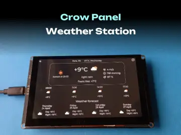
- Getting weather information from the OpenWeatherMap service and cyclically displaying the temperature every 15 seconds
- Manual or automatic adjustment of the brightness of the indicators and LEDs depending on the illumination.
- The ability to control 12 SW2812 LEDs, supports 3 modes static, rainbow and seconds
- Management and configuration via the web interface.
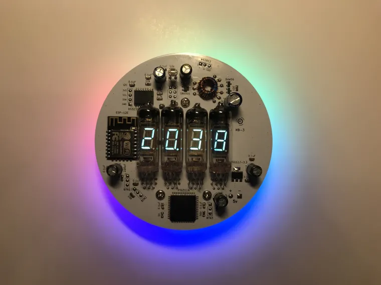
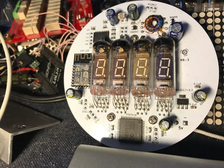
The watch is assembled on the ESP12E module(ESP8266). Using this module allows you to implement time synchronization using the NTP protocol and manage clock settings through a browser.
A special PT6311B driver is used to control the indicators, which provides dynamic display functions and brightness adjustment.
The glow supply of the indicators and the anode/grid voltage are generated by the converter on the SN6501. Linear stabilizers AMS1117-3.3 by 3.3 volts are used to power the watch. There are 2 of them in the circuit, one for powering the digital part, the second for the WS2812B LEDs
The DS3231 is used as a real-time clock. Which has a separate backup power supply to keep the clock running in the absence of the main power supply. The current consumption of the clock does not exceed 300 milliamps and depends on the brightness of the indicators and the operating mode.
A photoresistor is used as a light sensor.
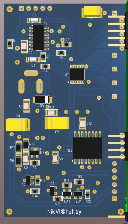
The board has connectors for connecting 3 buttons, an i2c bus, additional WS2812 LEDs and programming the ESP-12 module.
The connectors for the buttons have an additional power output, which allows you to use touch modules instead of buttons. Currently, only one BTN1 button has software support, when you click on it, the date is displayed. It is also possible to use these connectors for the 1-Wire bus.
The i2c bus is designed to connect additional sensors, temperature, humidity, pressure, etc.

More detailed: https://vk.com/@retromodding-chasy-na-vfd-indikatorah-s-wifi-iv-6-iv-2-iv-3-iv-3a-iv-8


