Add to cart
Board Type : GerberFile :
Layer : Dimensions :
PCB Qty :
Different PCB Design
PCB Thickness : PCB Color :
Surface Finish : Castellated Hole :
Copper Weight : 1 oz Production Time :
Total: US $
Elecrow community is a shared platform and we are not responsible for any design issues.

PCB Assembly

PCBA Qty: BomFile:
NO. OF UNIQUE PARTS: NO. of Components:
Assembly Cost: US $
Elecrow community is a shared platform and we are not responsible for any design issues.
Add to cart
3dPrintingFile : Size :
Unit : Volumn :
3D Printing Qty : Material :
Total: US $12.99
Elecrow community is a shared platform and we are not responsible for any design issues.
Add to cart
Acrylic Type : AcrylicFile :
Dimensions: Engrave:
Acrylic Qty :
Acrylic Thickness:
Acrylic Color:
Total: US $12.99
Elecrow community is a shared platform and we are not responsible for any design issues.
Add to cart
CNC Milling File : Size:
Unit: Volumn:
CNC Milling Qty : Material:
Type of Aluminum: Surface Finish:
Tolerance:
Surface Roughness:
Total: US $12.99
Elecrow community is a shared platform and we are not responsible for any design issues.
closed
user-img

cris

Published: Oct 06,2024

Switch based light sensor

This is an old circuit built with analog components.

ccc ccc
Copyright Info

Attribution-ShareAlike (CC BY-SA)

Read More⇒
  261
  1
  0
cover-img
 
  • thumbnail-img
  • thumbnail-img
 

Hardware Components

  • 2N2222

    X 1 fenxiang

Tools, APP Software Used etc.

  • Kicad

Story

Switch based light sensor


Hi!

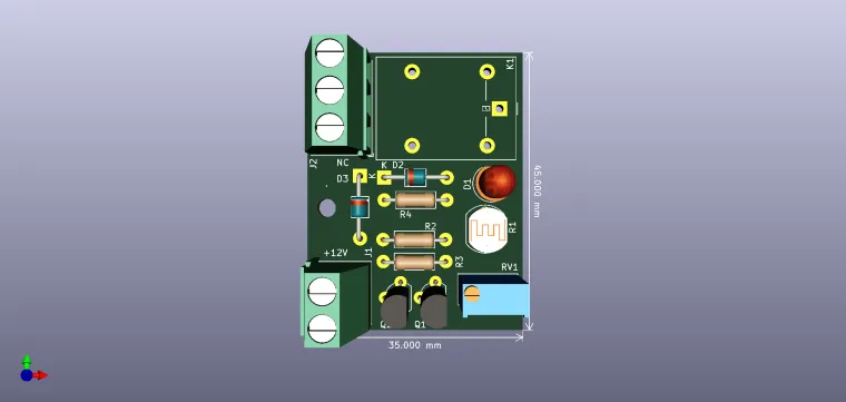
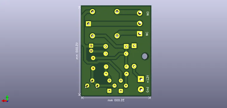
The circuit shown can be used to turn on the light in the garden, or some light panels / advertisements in the evening; or early in the morning when they need to be turned off; automatic switching on or off of the warning lights and more.

The circuit contains two amplifier stages with transistors.

The first floor detects the state of local lighting through the LDR photoresistor. In the dark, the value of photoresistor is about 50KΩ and in bright light below 500Ω. Together with the resistor RV1 forms an adjustable voltage divider from which the control signal based on the transistor is applied.

In the dark, the relay is triggered. When the photoresistor receives a light beam, it will increase the current that will be injected based on the transistor and cause a collector current. The threshold is set by adjusting the RV1 semi-adjustable. As the illumination decreases, the value of the LDR (photoresistor) resistance increases, the transistor Q1 will lock, Q2 will enter the conduction and will allow the relay to start, simultaneously with the LED lighting.

P.S. I'm not the original author of this circuit, I just drew it.

user-img

cris

+ Follow

Topic

View All
  • Comments( 0 )
  • Like( 1 )
/1000
Upload a photo:
You can only upload 1 files in total. Each file cannot exceed 2MB. Supports JPG, JPEG, GIF, PNG, BMP

You May Also Like

View All