Story
Stepper Motor Driver
Circuit description
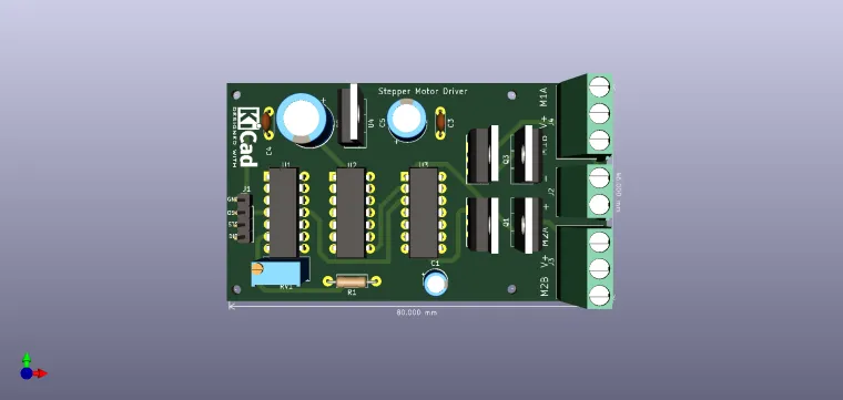
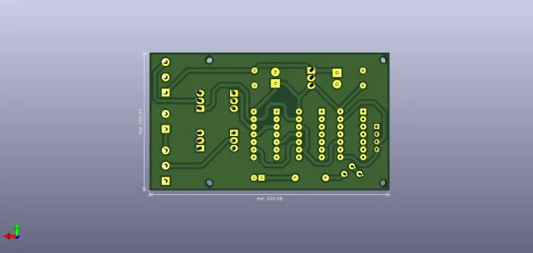
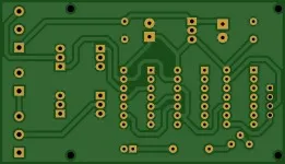
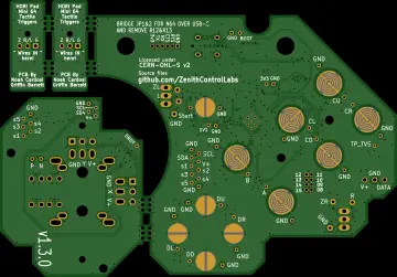
Like any motor, stepper motors consist of a stator and a rotor, but without brushes. Unlike conventional brushless DC motors, the variable electromagnetic field that controls movement is formed not by the switching of the coils by the brushes on the rotor, but by the way the pulses are applied to the stator coils. The stepper motor rotor can be with permanent magnet, a variable reluctant or a mixture of the two. By controlling the field between the stator and the rotor, a very precise one-way movement can be obtained. Therefore, stepper motors are supplied with rectangular voltage pulses of appreciable current. They are stepper motors whose pitch is 0.9 °; 1.8 °; 3.6 °, etc. Compared to the 360 ??° of a circle, a step of 0.9 ° involves, at a complete rotation, the execution of 400 individual steps, controlled by the control logic of the pulses applied on the four coils. , especially by thermal effect, which in a stepper motor, are important, the following observations are made; at low travel speeds (low frequency control) the stepper develops a very high torque at its shaft. If they are supplied with low voltage fixed (stabilized) voltage sources, no special problems occur; however, if the control frequency increases (travel speed increases) the torque decreases even more due to the high impedances of the coils, an effect manifested at high frequencies. Three power supply modes are possible, - powering the coils from a "chopper" (switching source), with very high voltage, so that at high speeds the filling factor increases in the source control, - power supply from the voltage source of high value in series with a ballast resistor - the resistor limits the current through the stator: - supply from a constant current source that will keep the current through the coils (the same, regardless of speed) if the speed increases and increases the voltage accordingly. There are disadvantages what regarding the first two methods (the realization of a switching source for inductive loads must be well tolerated, and a power series resistor denotes high power consumption and heat dissipation.) The use of a current source (at high control frequencies) is the most indicated. , it keeps the current constant through the coils (so constant torque), the voltage can take any values ??depending on the torque required by the motor. electrical call, there is an oscillator made NAND gate U1B, the frequency being controlled from R1. With the help of this oscillator the annual control of the stepper movement or the driver test is allowed (via the OSC pin). For this operation the OSC pin (from J1) is connected to STP, and DIR to GND. To reverse the direction of rotation, DIR is connected to + 5V. IRFZ44 transistors can switch without radiator load currents up to 5... 6A. The supply of logic circuits is done with + 5V from L7805. The minimum supply voltage of the assembly is 8V, and the maximum (imposed by LM7805) is 35V. The maximum supply voltage of 35V is applied to connector J2 (in the middle of the block connector bar). Connect the wires of the stepper to each 3-pin connector at both ends of the PCB. The V + signal is common. The other signals corresponding to the coils are M1A and M2A, respectively M1B and M2B.
Enjoy it!


