


Story
In every game, reaction time is crucial. Quick responses to the ball or mouse click lead to victory. To improve response time, eye and hand coordination, I created a small gaming device.
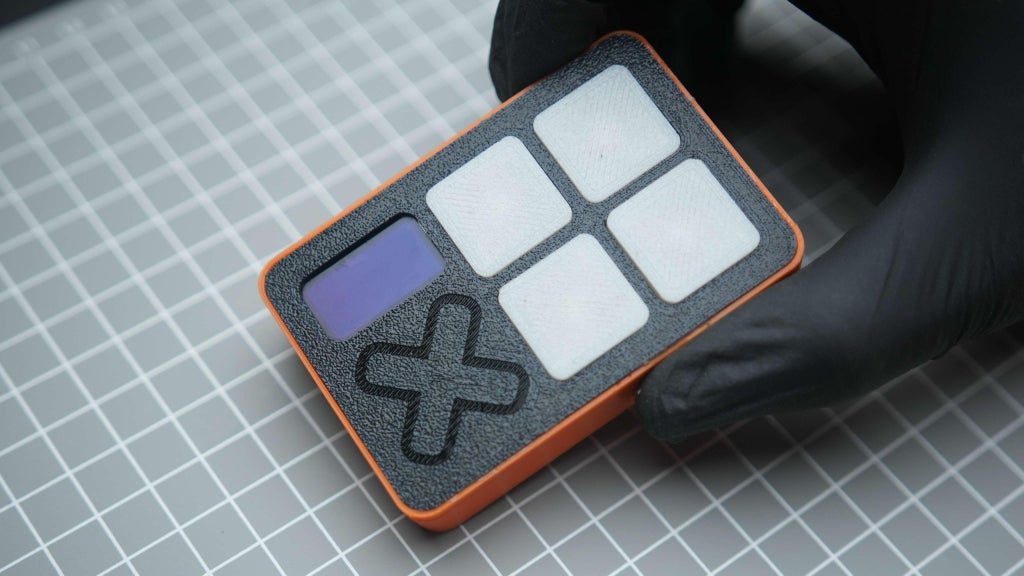
we are going to create a credit card-sized portable reaction time game device for better eye and hand condition
After powering up, the user needs to press any of the 4 buttons to start the game. The OLED will display a "press any button" message during this time.
Once any button is pressed, there will be a When I first thought about making this device, I originally thought of making it the size of a credit card. I have tried to fit this project to that extent. Various button configurations were thought of and arrived at. A 3-second countdown is displayed on the OLED screen in reverse order: 3, 2, 1. After the countdown ends, the screen will display "GO."
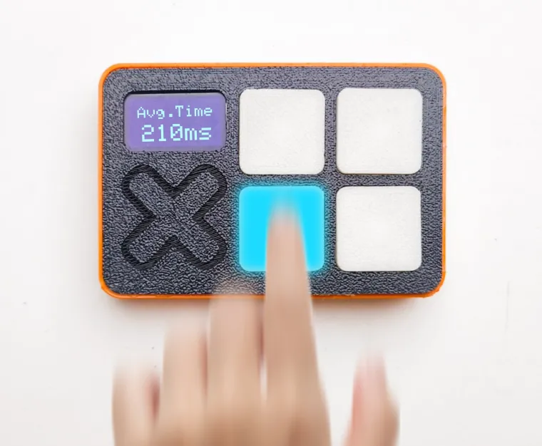
When the game starts, an LED inside one of the buttons will light up randomly. The user must press the button with the illuminated LED as quickly as possible. The time between the LED turning on and the user pressing the button will measure the reaction time in milliseconds. After registering the first reaction time, we need to wait 0.5 seconds to light up the other switch. This needs to happen 4 times. All four reaction times need to be averaged to show the final reaction time. The switch that needs to be pressed will be random every time. After averaging this reaction time it needs to show this time in milliseconds. If you press any other button you can restart the game
The best i can do is 220ms let me know if you make one
Supplies
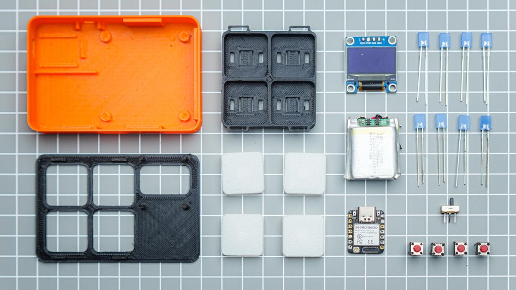
parts
- Seeed studio xiao esp32c3
- Slide switch
- B-7000 multi-Purpose glue
- 30 AWG wires
- 8* square led
- push button
- 500 mah battery
- B-7000 Multi-Purpose Glue
Tools
- Soldering iron kit
- Wire cutter
- Third-Hand Soldering Tool
- 3d printer ( black , white,orange PLA)
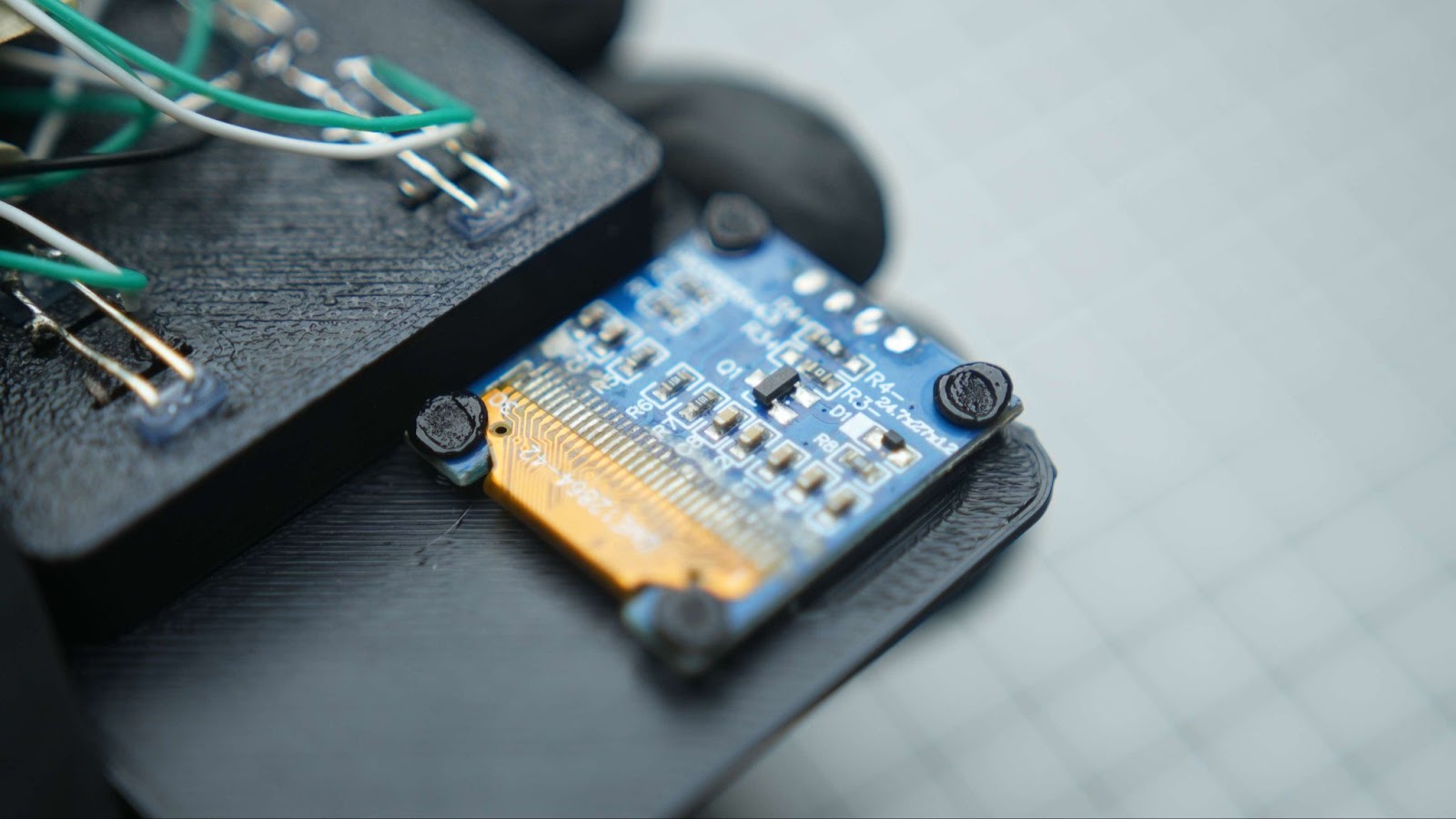
Step 1: Designing and 3d Printing
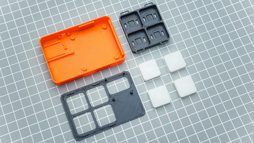
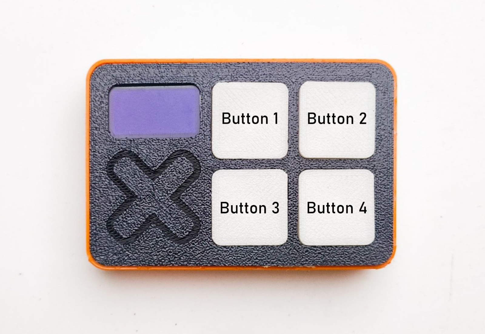
When I first envisioned creating this device, I aimed to make it the size of a credit card. . I considered various button configurations and settled on this design. The front panel, bearing my logo, accommodates the OLED module and button tray using the Heat stake method. This should be printed in black. The low-profile buttons incorporate 2 LEDs for illumination and need to be printed in black. The main body houses the microcontroller, battery, and power switch. It also accommodates the front panel button assembly.
I utilized Fusion360 for the design of this project. After designing, I exported it into an .STL file for 3D printing. I used my Anycubic Kobra to Neo 2 for 3D printing all the files, employing PLA for printing all parts of the project in 3 colors. The buttons need to be printed in white for optimal illumination. You can access all design files and the .STL file below."
Step 2: Flashing the Code to Xiao Eps32c3
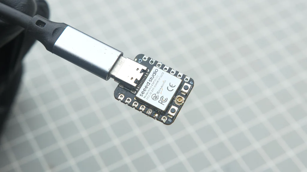
I always like to upload the code to the microcontroller before assembly. I am using Arduino IDE to flash the code. follow these tutorials for setting up IDE for Seeed Studio XIAO esp32c3 and learn more about this board
#include <SPI.h>
#include <Wire.h>
#include <Adafruit_GFX.h>
#include <Adafruit_SSD1306.h>
#define SCREEN_WIDTH 128 // OLED display width, in pixels
#define SCREEN_HEIGHT 64 // OLED display height, in pixels
#define OLED_RESET     -1 // Reset pin # (or -1 if sharing Arduino reset pin)
#define SCREEN_ADDRESS 0x3C ///< See datasheet for Address; 0x3D for 128x64, 0x3C for 128x32
#define SSD1306_NO_SPLASH
Adafruit_SSD1306 display(SCREEN_WIDTH, SCREEN_HEIGHT, &Wire, OLED_RESET);


// Define push buttons and LEDs pins
const int buttonPins[4] = {D0,D1,D2,D3};
const int ledPins[4] = {D7,D8,D9,D10};


unsigned long reactionTimes[4];
int currentRound = 0;


void setup() {
  // Initialize buttons and LEDs
  for (int i = 0; i < 4; i++) {
    pinMode(buttonPins[i], INPUT_PULLUP);
    pinMode(ledPins[i], OUTPUT);
    digitalWrite(ledPins[i], LOW);
  }


  // Initialize the OLED display
  display.begin(SSD1306_SWITCHCAPVCC, SCREEN_ADDRESS);
  display.display();
  delay(2000);
  display.clearDisplay();


  // Show the initial message
  display.setTextSize(2);
  display.setTextColor(WHITE);
  display.setCursor(0, 0);
  display.println(" Press any");
  display.println(" button to");
 display.setTextSize(3);
display.setCursor(28, 38);
display.print("PLAY");


  display.display();


  // Wait for any button press to start the game
  waitForAnyButtonPress();

  // Start the countdown
  startCountdown();
}


void loop() {
  if (currentRound < 4) {
    // Select a random LED to light up
    int randomLED = random(0, 4);
    digitalWrite(ledPins[randomLED], HIGH);


    unsigned long startTime = millis();
    while (!digitalRead(buttonPins[randomLED]) == LOW) {
      // Waiting for the correct button press
    }
    unsigned long endTime = millis();
    digitalWrite(ledPins[randomLED], LOW);


    // Record the reaction time
    reactionTimes[currentRound] = endTime - startTime;
    currentRound++;

    delay(500); // Wait 0.5 seconds before lighting up another LED
  } else {
    // Calculate and display the average reaction time
    unsigned long totalTime = 0;
    for (int i = 0; i < 4; i++) {
      totalTime += reactionTimes[i];
    }
    unsigned long averageTime = totalTime / 4;


    display.clearDisplay();
    display.setCursor(15, 9);
    display.setTextSize(2);
    display.setTextColor(WHITE);
    display.print("Avg.Time");
    display.setTextSize(3);
    display.setCursor(19, 31);
    display.print(averageTime);
    display.println("ms");
    display.display();


    // Wait for any button press to restart the game
    waitForAnyButtonPress();
    currentRound = 0;  // Reset the game
    startCountdown();
  }
}


void waitForAnyButtonPress() {
  bool buttonPressed = false;
  while (!buttonPressed) {
    for (int i = 0; i < 4; i++) {
      if (digitalRead(buttonPins[i]) == LOW) {
        buttonPressed = true;
        break;
      }
    }
  }
}


void startCountdown() {
  display.clearDisplay();
  for (int i = 3; i > 0; i--) {
    display.setCursor(41, 3);
    display.setTextSize(8);
    display.setTextColor(WHITE);
    display.println(i);
    display.display();
    delay(1000);
    display.clearDisplay();
  }
  display.setCursor(20, 4);
  display.setTextSize(8);
  display.setTextColor(WHITE);
  display.println("GO");
  display.display();
  delay(1000);
  display.clearDisplay();
}
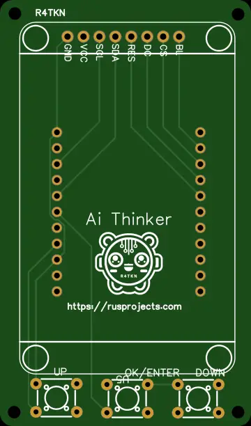
Step 3: Wiring Diagram
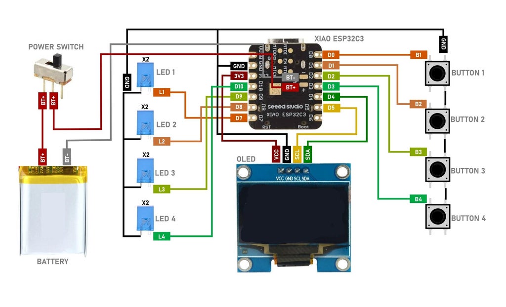
Here is the full wiring diagram of the project. The LED I am using here only draws below 15mA, so in total, the LED is using 30mA. The GPIO can handle a maximum of up to 40mA. If you use any other LEDs that need more current than this, it is better to use a 220-ohm resistor on the GPIO.
have 4 push buttons with the following connections:
- Push button 1 is connected to D0
- Push button 2 is connected to D1
- Push button 3 is connected to D2
- Push button 4 is connected to D3
I also have 4 LEDs with the following connections:
- LED1 connected to D7, which will light up for button 1
- LED2 connected to D8, which will light up when button 2
- LED3 connected to D9, which will light up when button 3
- LED4 connected to D10, which will light up when button 4
Additionally, I have a 128x64 pixel OLED screen that will display the score and game information.
we are also using the build in BMS in the xiao for recharging the battery so don't panic it is not a fire hazard
here is the buttons placement for reference
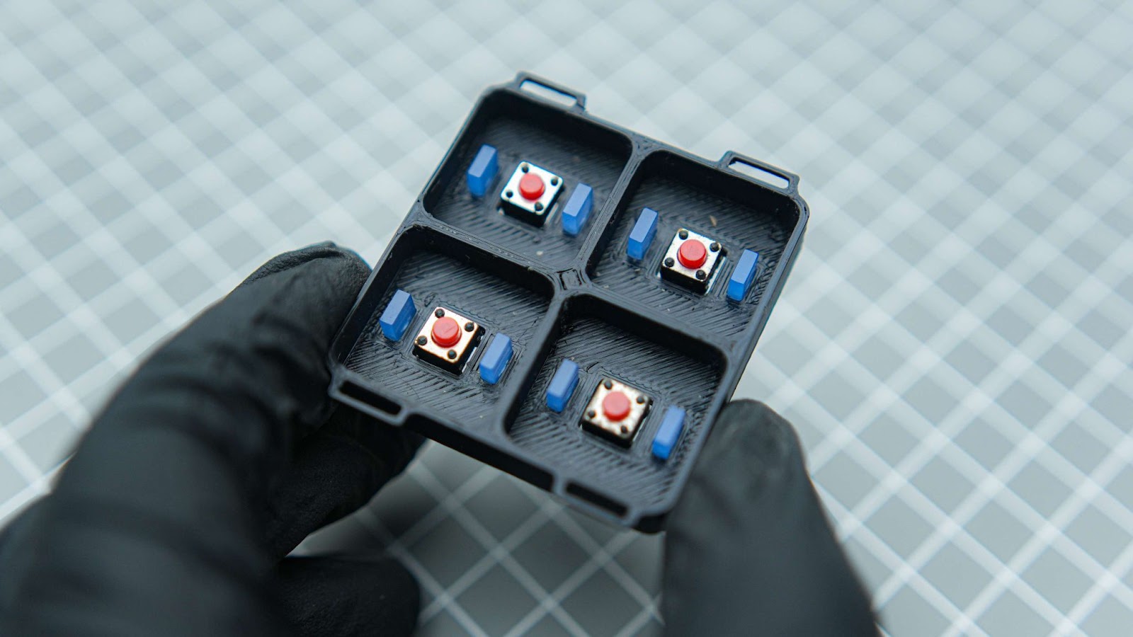
Step 4: Switch Tray Assembly
Make sure to place all four switches into the slots in the 3D printed switch tray.
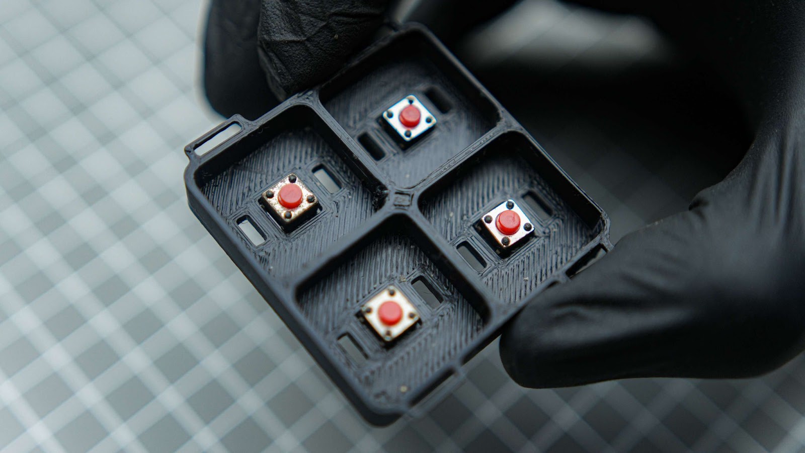
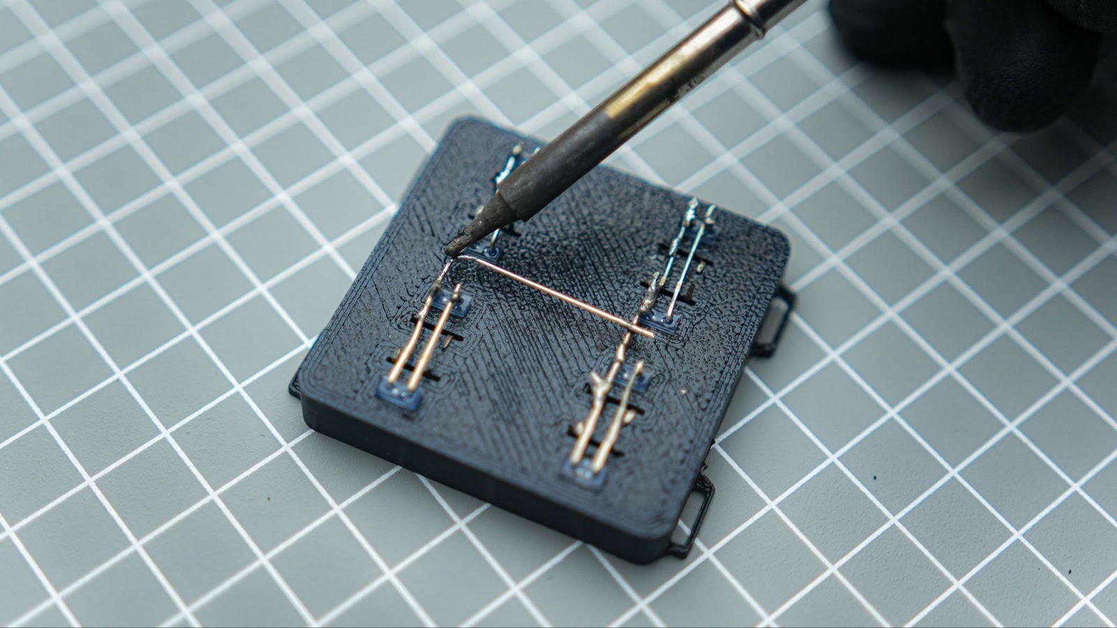
Band the top right and bottom left corners of the push button pin. Perform the same action on all of the switches.
Insert all of the LEDs into the slot, ensuring that the LED cathode is on the top.
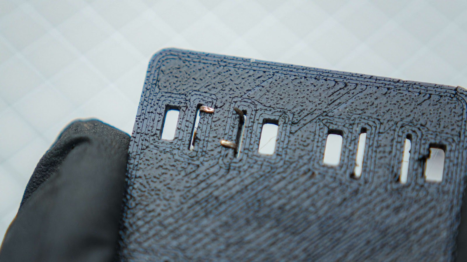
To connect the LED to the ground pins of the push button, bend the cathode terminal pin and solder it. Use this method to connect the buttons and other LED pins. Repeat this technique to connect all other ground pins.
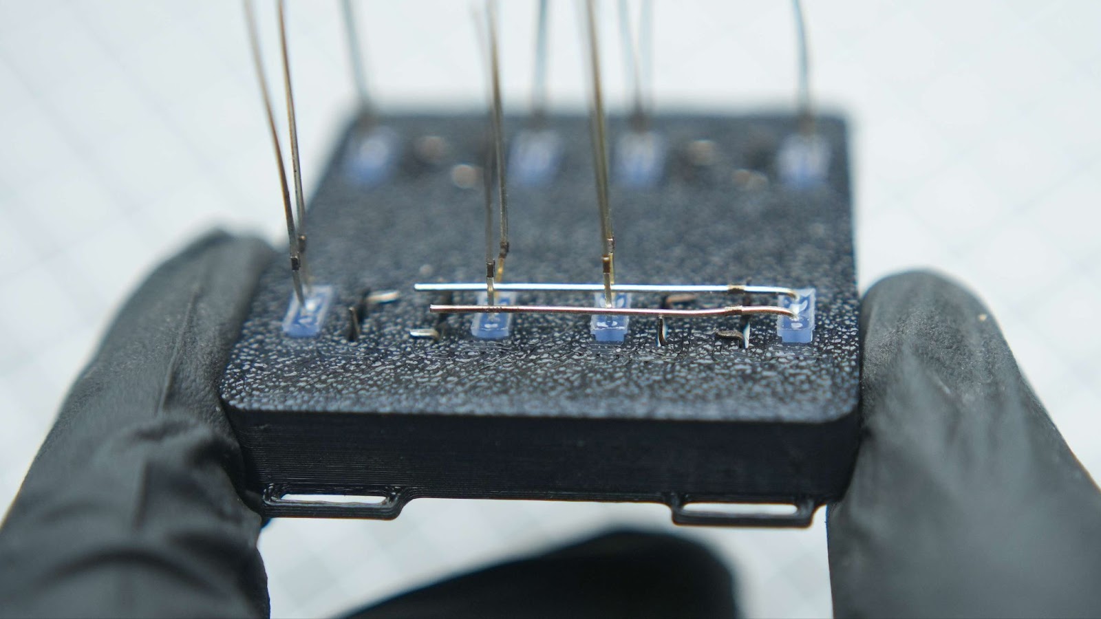
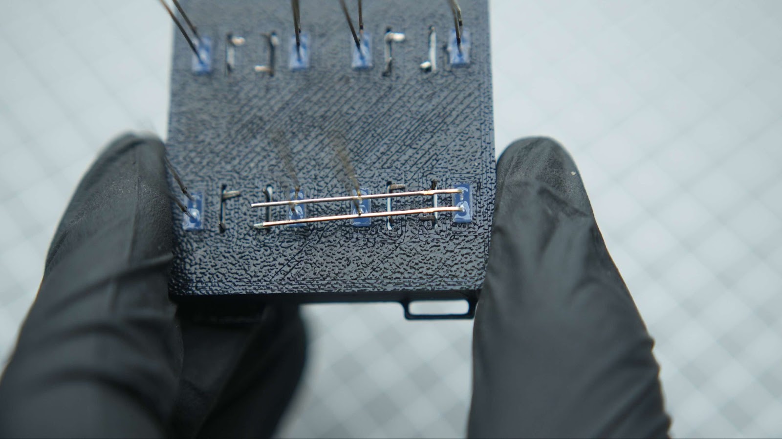

Please ensure to connect both of the ground pins.
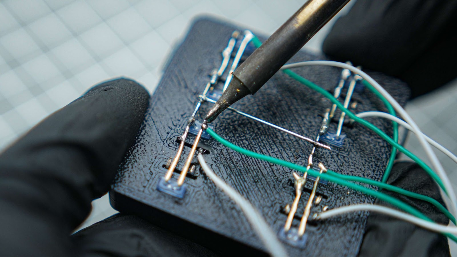
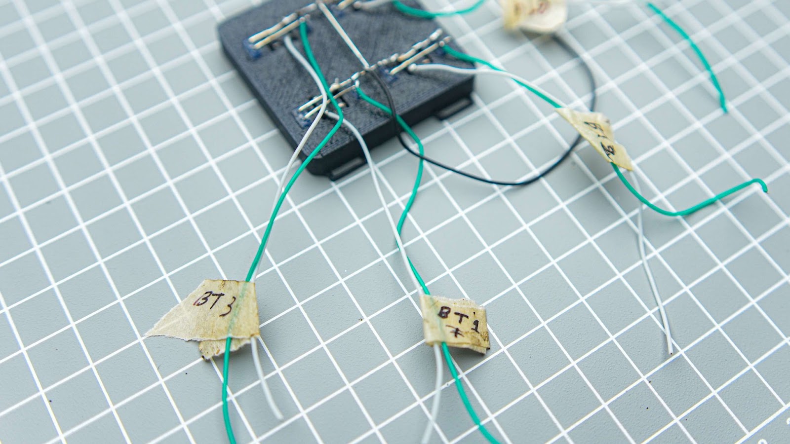
Use 8 cm wires to solder the switch and LED pins. Tag them for easy identification during assembly, such as BT1, LED 1, GND, etc.
Step 5: Front Panel Assembly
Place all 4 button caps into the front panel and then place the button tray onto the front panel.
Put the OLED screen into the Front Panel
Step 6: Heat Stake Method
We will be using the heat staking method to secure the OLED screen and the button tray. We need to melt plastic using a soldering iron to attach our OLED module and the button tray. Carrying out this process in a well-ventilated area is recommended. Additionally, it is better to use an old soldering iron for this task."
Step 7: Battery and Power Switch
Solder the battery +Ve terminal to one terminal of the power switch. Connect the other terminal of the power switch to the BT+ of XIAO. Also, connect the -Ve of the battery to the BT- of XIAO.
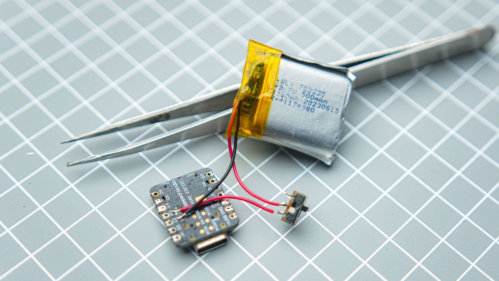
Please ensure that you glue the battery, XIAO ESP32C3, and the power switch into the 3D print. the power switch can be placed in ti small gap near the xiao
Step 8: Connecting the GPIO
Now, solder the wires from the front panel to the Xiao according to the circuit diagram. I cut the long wires and placed the front panel near the main body for easy assembly.
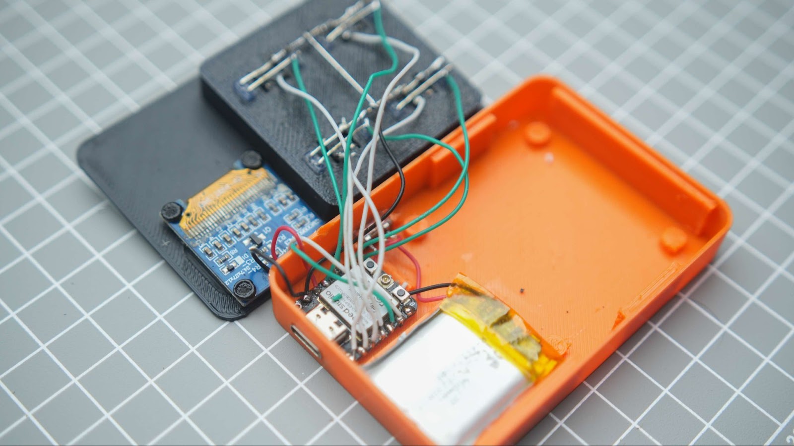
Step 9: Finishing the Assembly
Apply glue to the sides of the main body and insert the front panel. You may need to manage the wires for a proper fit.
Step 10: Final Though
Well, this is one of the first game projects I have completed. I like the small size of it, and it will always be on my desk to help me stay focused.