

Story
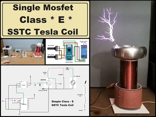
A Solid State Tesla Coil (SSTC) is a type of Tesla coil that uses solid-state components such as transistors, diodes, and capacitors to generate high-voltage, high-frequency alternating current electricity. They have higher efficiency, the possibility of long-term work, as well as compact dimensions. SSTCs come in various types and designs, each with its own characteristics and applications. This time I will describe to you how to make a Tesla coil that works in the so-called class-E, which in addition to being simple and cheap to make, it is also very efficient if is well adjusted. The original design is by Richie Brunett followed by several versions including that of Stevie Wards , which uses Antenna feedback, and PLL. I decided to make the LabCoatz version, based around an adjustable Schmitt trigger oscillator with a range of 100kHz-5MHz.
And as usual, I adapted the project based on the materials I had at the moment, and at the same time simplified it considerably. However, the end result is excellent and with a voltage of 70V - 90V the length of the sparks is 15 to 20cm, which is significantly more than the one in the original project. Due to the fact that I did not use an interrupter, in this case there is no option for an audio modulator, which is also conditioned by the cheap mosfet driver IC TC426.
And similar to any tesla coil, the basic parts are the primary and secondary coils. In this particular case, the primary consists of 20 windings of copper wire with a diameter of 2.5 mm wound on a plastic cylinder with a diameter of 11 cm. The secondary contains 1300 windings of insulated copper wire on a plastic body with a diameter of 7cm and a height of 20cm. The diameter of this wire is 0.14 mm. The calculated resonant frequency of the secondary together with top load is about 260KHz, and in practice somewhat higher.
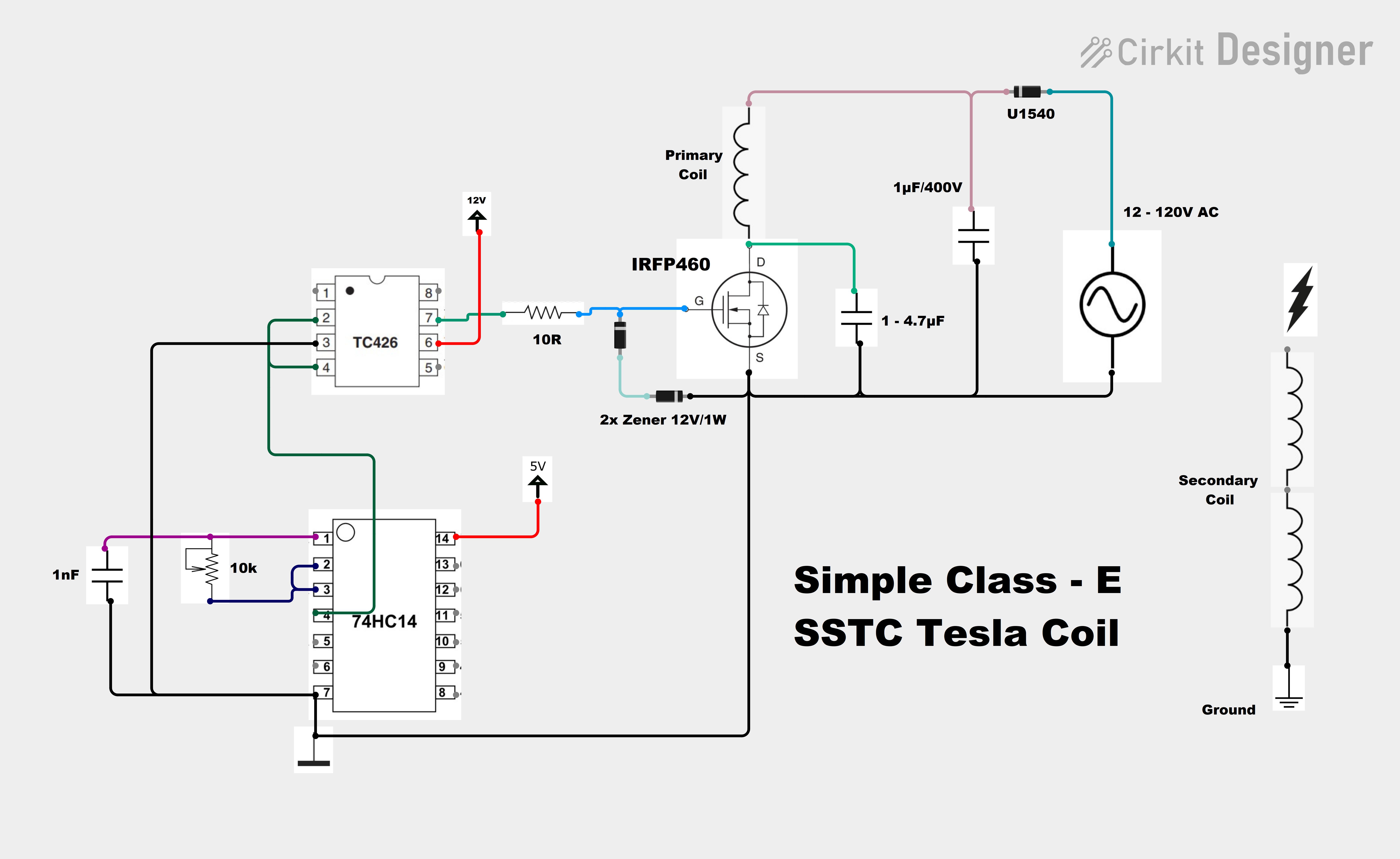
The drive part consists of several components:
- adjustable Schmitt trigger oscillator with a range of 50kHz-2.5MHz made with 74HC14 hex inverter IC.
- tp267 cheap mosfet driver IC.
- Powerful mosfet I used IRFZ, but it is better to use more powerful IRFP460.
- a polypropylene capacitor with a capacity of 1 nf or more depending on the tuning.
- 7805 CMOS IC power supply stabilizer
- 12V power supply for the oscillator and mosfet driver,
- and to power the mosfet and the primary coil, instead of full wave I use a half wave single diode power supply with a small 1µF filter capacitor primarily due to the fact that I could not use an interrupter due to the lack of an Enable pin on the mosfet driver IC.
If you want to ideally adjust the Tesla coil, you definitely need a two-channel oscilloscope and a lot of patience. The setup method is explained in detail on the original project page. I will explain the basic setup procedure, assuming we don't have any instrument. First, we apply a voltage of about twenty volts to the mosfet, and with a CFL bulb close to the transformer, we turn the potentiometer until the bulb lights up. We keep spinning until we get maximum intensity.
Next, we change the number of windings of the primary also looking for the highest intensity of the bulb, but we should keep in mind that the number of windings should not be less than 3 or 4 because of the excessive current that can flow through the mosfet. Let the polyester capacitor that forms the E class be a few (4.7) nanofarads, and then we can experiment with smaller values. Now we can gradually increase the voltage, controlling the temperature of the mosfet. In my case, the maximum voltage for reliable operation of the device was about 75V.
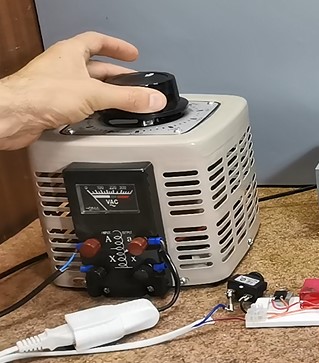
Let me mention that the use of a variac when testing any Tesla Coil is of great help, not only in terms of testing, but also saving relatively expensive semiconductor elements, so if we want to go a little more seriously in this area, the variac is the most important component.
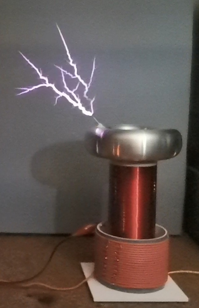
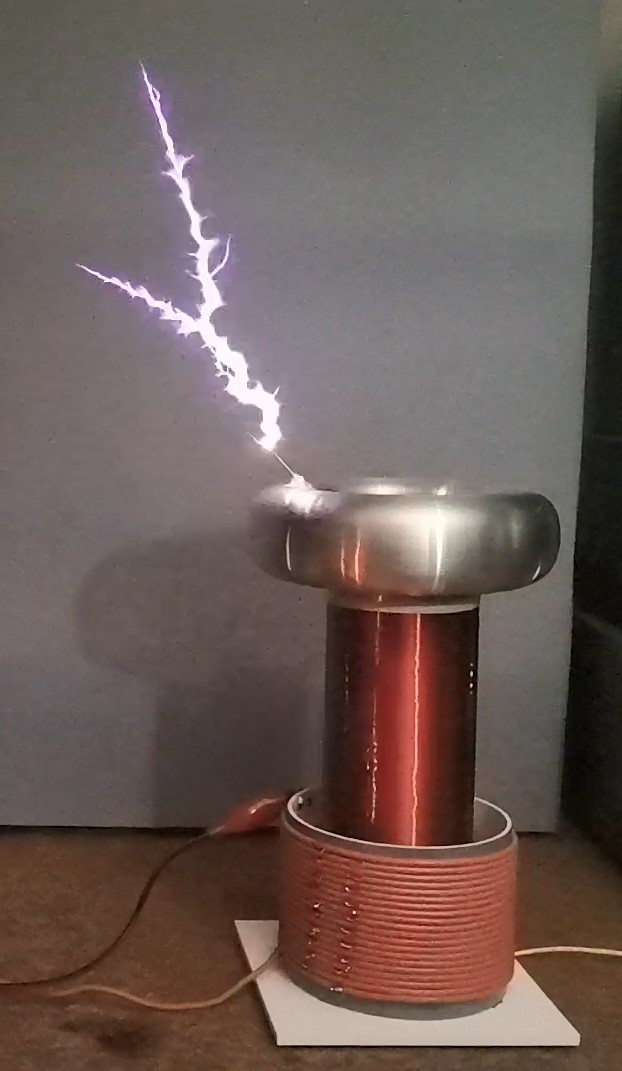
And now the interesting part, let's see how the device works in real conditions:
As can be seen this tesla coil generates a nice branched spark, similar to that of a spark gap tesla coil, which is probably due to the low resonant frequency of the secondary as well as the pulsating power supply of the mosfet.
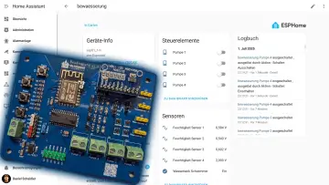
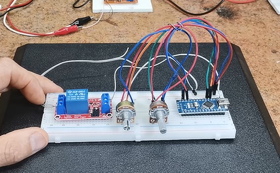
At the beginning I mentioned why I couldn't use a classic interrupter, so I made a very simple Arduino project with a relay and two potentiometers that can be used to change the duration of the pulse and the pauses between the pulses.

In this way the contacts of the relay periodically interrupt the power supply from the oscillator and act as a kind of mechanical interrupter. Due to the slowness of the relay, the maximum frequency of this interrupter is limited to a few hertz.
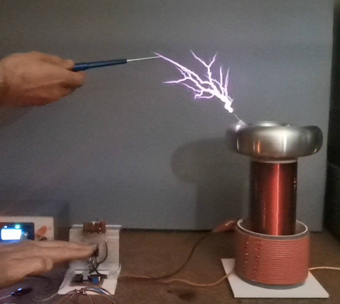
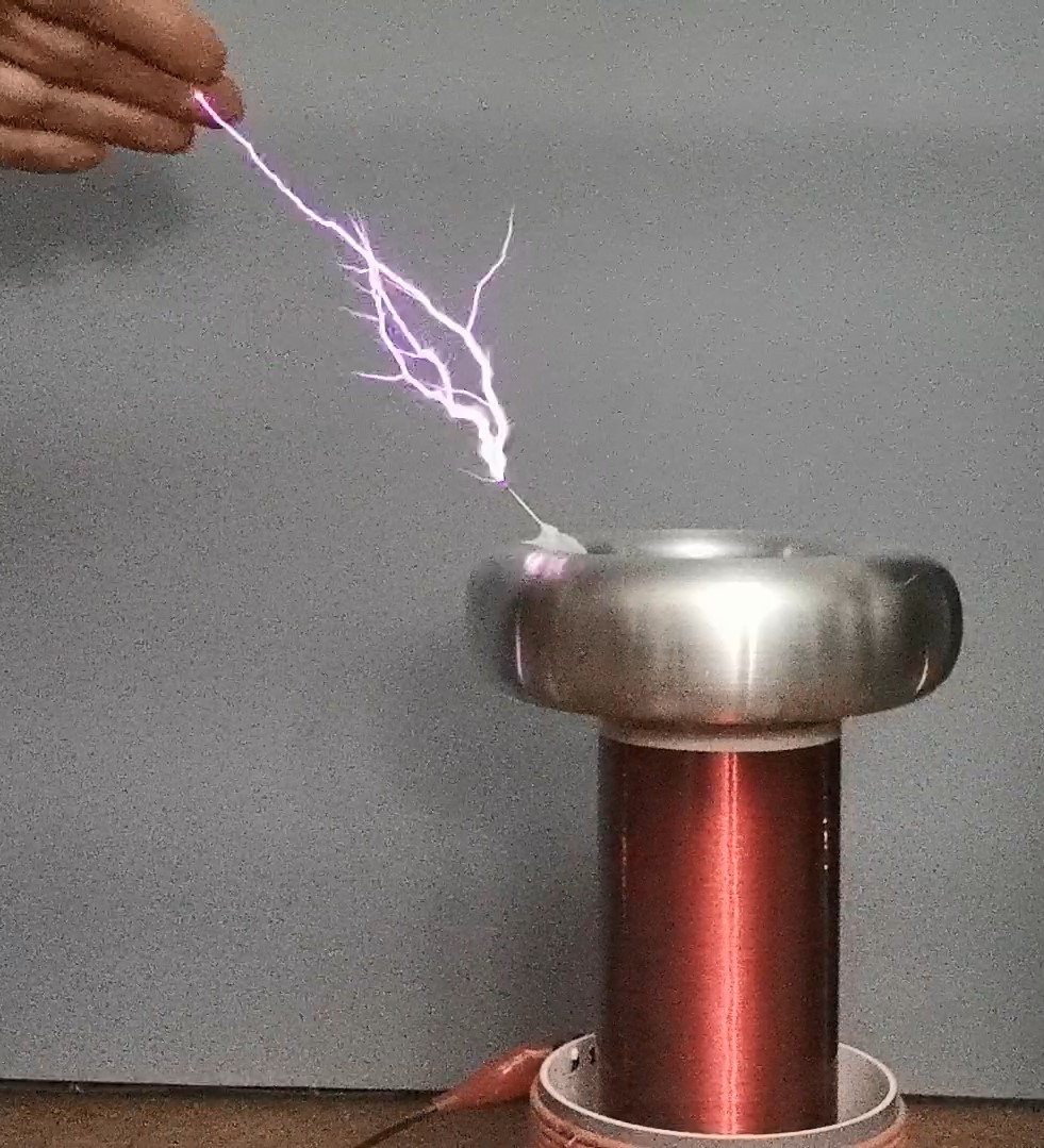
The following is a presentation of the operation of this device with an interrupter
Now I can also increase the voltage of the Mosfet. and the sparks are significantly larger
In this mode of operation the mosfet is almost cold. I guess if I used IRFP460 the result would be much better.
And finally, a short conclusion:
This Tesla coil, although apparently simple to make, actually requires a lot of knowledge, patience and tools to set it up ideally. However, even with less experience, it can be tuned quite well with the trial and error method. In fact, a large part of the pleasure in making this device is due to the long-lasting and unfortunately often expensive way of setting it up. Therefore, in the end, the visual effect is really amazing.
SAFETY NOTE: Please do not attempt to recreate the experiments shown on this video unless you are familiar with High Voltage Safety Techniques! Direct Current even above 60V maybe lethal, even when the AC supply voltage has been disconnected due to the stored energy in the capacitors. I have no responsibility on any hazards caused by the circuit. Be very careful. This is a humble request.