Story
Simple Voltage Indicator with LEDs Bargraph
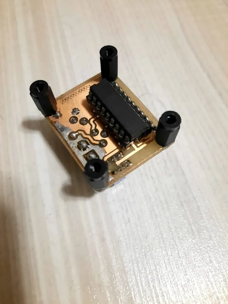
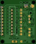
Hello! This is my Project!. There are situations when it is necessary the display in one form or another of an electrical size or non-electric. Display mode it is chosen taking into account several aspects such as: speed of variation a of that size, the required accuracy measurements, ease of reception by information observer etc. Graphic display of electronic quantities trice / nonelectric wins lately more and more ground because it is more suggestive. Integrated circuits indicates ten step voltage steps given by the value of the reference voltage internal adjustable from the outside. Since the ten outputs provide in load a controlled current, can be ordered LEDs of different colors or segments of liquid crystals (LCD). The practical applications are simple, requiring a small number of external passive. The assembly represents a level indicator with application in many fields. It is made around the integrated circuit LM3914 (similar to LM3915, LM3916). All these three integrated circuits are the drivers for 10 LEDs with the possibility of displaying either the LED bar type or the dot. The difference between the three integrated is given by the law of LED lighting: LM3914 has a linear variation, LM3915 also has logarithmic variation but with scale head at 0dB and LM3916 has a logarithmic variation with scale head at + 3dB. The assembly can be supplied with a direct voltage between 9 and 15V. The potential of pin 9 determines the display mode: if pin 9 is connected to the supply voltage the display is in the form of a bar and if it is connected to ground the display is made in the form of a point. To adjust the level indicator se connects a voltmeter between pin 7 and GND. Adjust the semi- adjustable RV1 so that the voltage the reference from pin 7 to be larger or equal to the maximum voltage level from the entrance, watching the ignition the ten LEDs corresponding the level applied Areas in which it can be used the level indicator are numerous, or for example, it can be used as a tool on board cars (tachometer, voltmeter) or together with a detector peak or average value for of evaluation of alternating current signals (VU-meters, powermeters, etc.). The electrical scheme of the assembly and the scheme of placement of the parts on the wiring is above. The list of components is above. Careful! No negative voltages will be applied to the mounting input. Bill of materials "Component Count:" "8" "Ref" "Value" "BAR1" "HDSP-4830_2" "J1" "Battery" "J2" "SW" "J3" "SP" "R1" "3k" "RV1" "5K" "RV2" "50K" "U1" "LM3914"
Have fun with it!


