


Story
I have got a stereo turntable and some vinyls and then I realized that if I want to listen to them, I need a preamplifier. The turntable itself doesn't contain it. There is a big science about which preamplifier to use and why, everybody recommends something else. Then I got a recommendation for Actidamp Mk2 that was published in the magazine "Amatérske rádio" (A02/90) and of course used components of that time. However, it is still a very good circuit that is also often built by people nowadays.
Unfortunately, the complete guide with schematic and PCB was nowhere to be found. Any information have just disappeared from the internet after all those years.
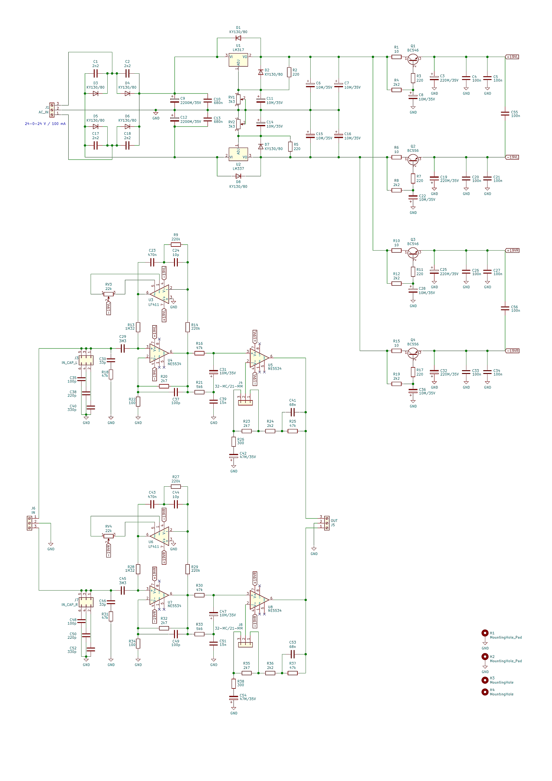
So I used one circuit I found that contained errors and fixed them. I also made some other improvements. I used potentiometers instead of fixed resistors for LM317 and LM337, so that the supply voltages can be set easily and precisely to be as symmetrical as possible. Then I used all recommended components in the circuits of LM317 and LM337 to improve their stability and lower any noise. And, finally, I replaced the rectifier bridge with individual diodes. It's because there are many bridges on the market and it would not be very good to make the circuit dependent on one specific type of bridge. On the other hand, everybody has got plentiful of diodes. Any diodes can be used that can withstand at least around 50 V in reverse, for example 1N4007. I used old Tesla KY130/80 because I have many of them.
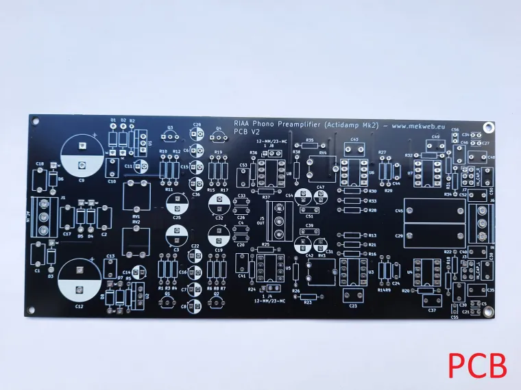
I have re-drawn the schematic into KiCad and offer it for download on this page (button below). This way anybody can make the PCB at home, or order the PCB at a professional company. Just generate Gerber output from KiCad and you are ready to go.
The preamplifier is suitable for both MM (moving magnet) and MC (moving coil) cartridges. You just have to connect the correct pin headers in both channels according to your cartridge type. I used jumpers from old PCs for that.
There is a so-called capacitance multiplier in the supply voltage rails, which ensures the supply voltages are as smooth as possible. That's important because any remains of AC will cause hum in the output.
This is the schematic (larger version can be downloaded down below):
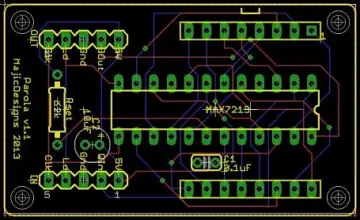
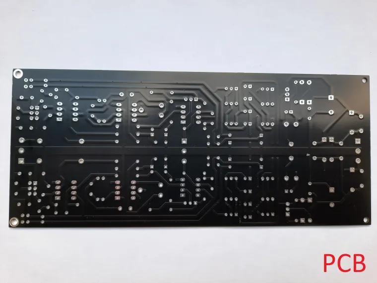
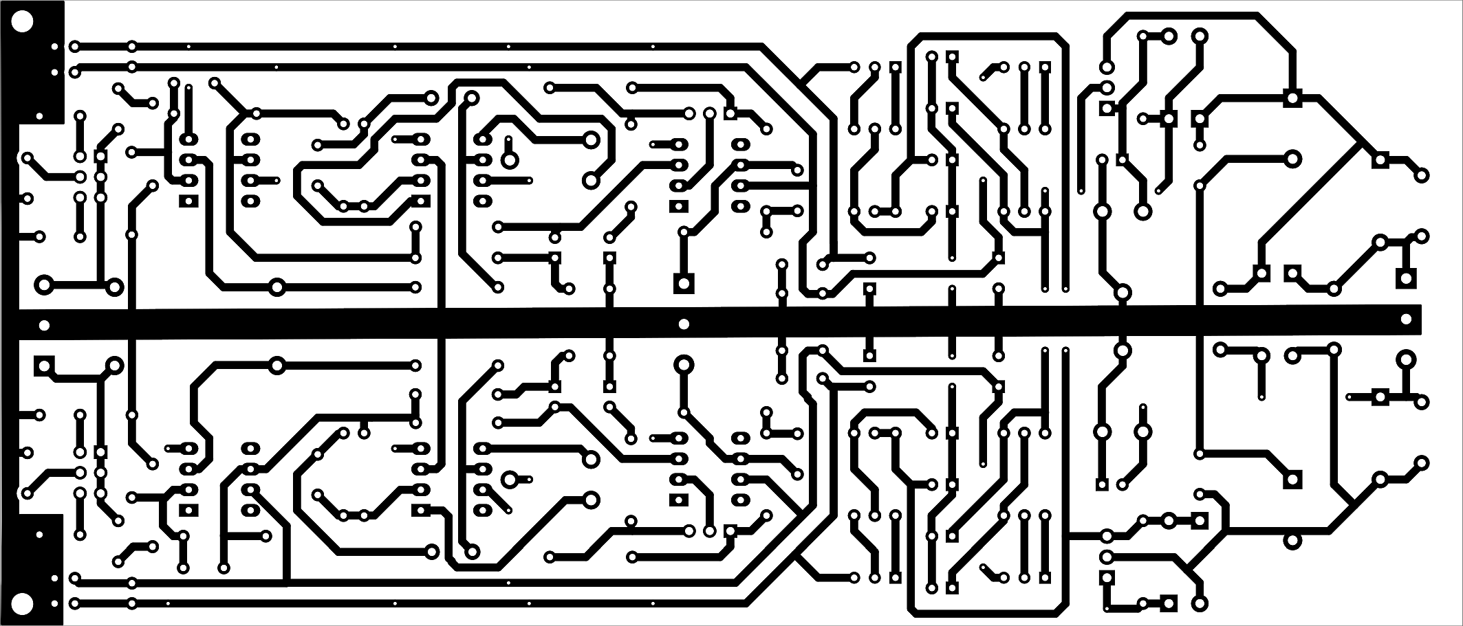
And this is the PCB (180 x 77 mm):
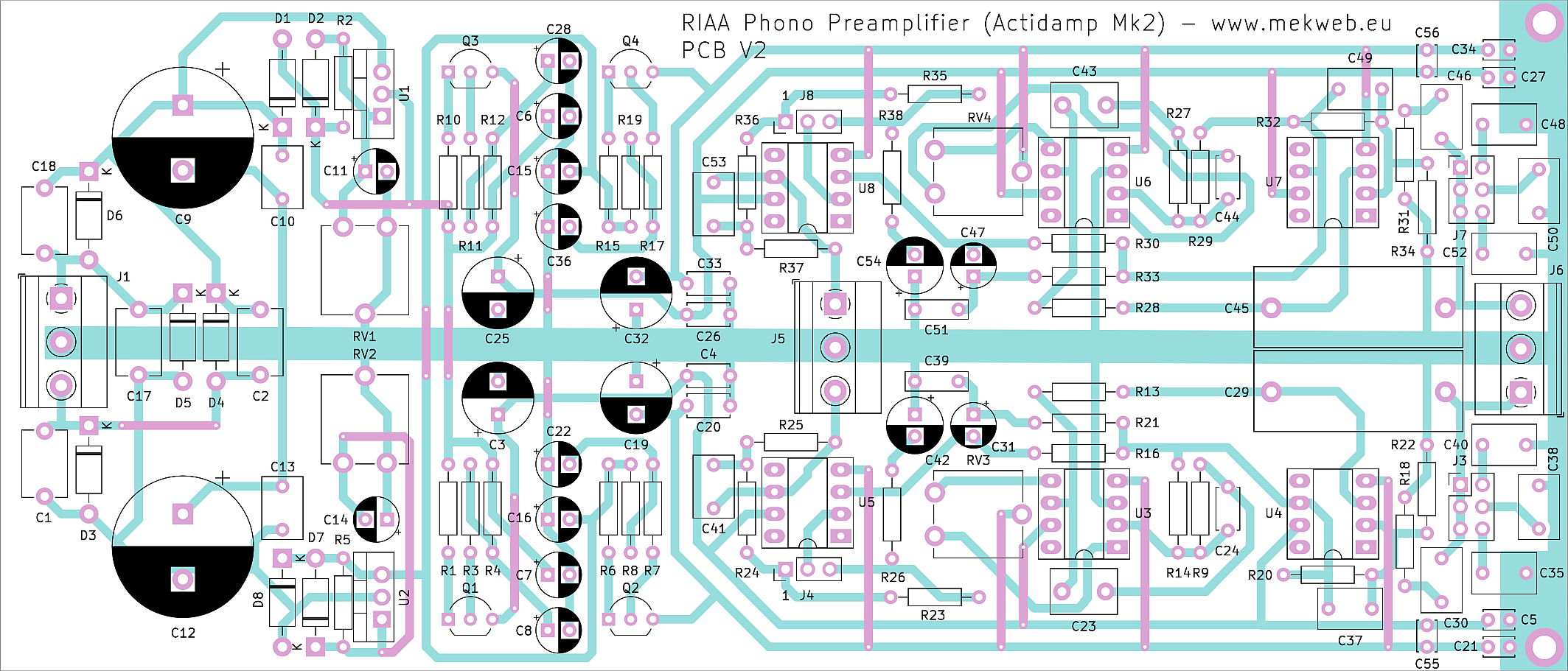
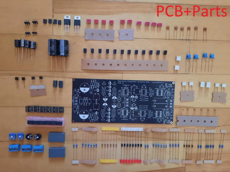
Bill of materials (BOM)
| C1, C2, C17, C18 | 2n2 |
| C3, C19, C25, C32 | 220M/35V |
| C4, C20, C26, C33 | 100n |
| C5, C21, C27, C34, C55, C56 | 100n |
| C6, C7, C8, C11, C14, C15, C16, C22, C28, C31, C36, C47 | 10M/35V |
| C9, C12 | 2200M/35V |
| C10, C13 | 680n |
| C23, C43 | 470n |
| C24, C44 | 10p |
| C29, C45 | 3M3 |
| C30, C46 | 33p |
| C35, C37, C48, C49 | 100p |
| C38, C50 | 220p |
| C39, C51 | 15n |
| C40, C52 | 330p |
| C41, C53 | 68n |
| C42, C54 | 47M/35V |
| D1, D2, D3, D4, D5, D6, D7, D8 | KY130/80 / 1N4001-7... |
| Q1, Q3 | BC546 |
| Q2, Q4 | BC556 |
| R1, R6, R10, R15 | 10 |
| R2, R3, R5, R7, R11, R17 | 220 |
| R4, R8, R12, R19, R24, R36 | 2k2 |
| R9, R14, R27, R29 | 220k |
| R13, R28 | 1M32 |
| R16, R18, R25, R30, R31, R37 | 47k |
| R20, R23, R32, R35 | 2k7 |
| R21, R33 | 5k6 |
| R22, R34 | 100 |
| R26, R38 | 300 |
| RV1, RV2 | 4k7 |
| RV3, RV4 | 22k |
| U1 | LM317 |
| U2 | LM337 |
| U3, U6 | LF411 / TL071 |
| U4, U5, U7, U8 | NE5534 |
| J1, J5, J6 | 3-pole PCB terminal block |
| J3, J7 | 2x3 pin header 2.54 mm |
| J4, J8 | 1x3 pin header 2.54 mm |
Original sources mention that MAC156 can be used instead of LF411 (I haven't tried it). LF411 is long obsolete, today's replacement may be TL071. Passive components must be chosen and measured before use, such that they are as precise as possible and as much the same as possible in both channels. It's important for preserving the RIAA characteristics.
Do the assembly as usual, and use sockets instead of op-amps. When turning on the first time, of course leave the sockets unpopulated. Set the supply voltages to around 19 V (as much symmetrical as possible) by using potentiometers near LM317/LM337. Then connect all 4 jumpers according to your cartridge type. Measure all voltages on the pins of the sockets - find out if the expected positive/negative voltages are present where they should be. If anything is wrong, check your PCB assembly for unintentional bridges or bad contacts. If everything is OK, populate the op-amps and measure current sourced from the transformer - both rails should be around 50 mA. Then, connect a DC millivoltmeter on the L output (after that, also the R output), and use the potentiometer in that channel to set up the voltage as close to zero as possible (typically lower than 1 mV). Then you can connect the input and output, and it should play.
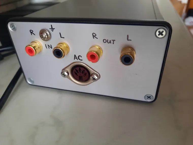
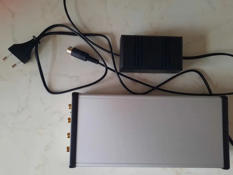
You can use a transformer with output voltage around 24-0-24 V (symmetrical) as the power supply, with max. current around 100-200 mA. I used a small transformer from some dismantled electronic device and mounted it inside a universal plastic box - see photo below. It's generally recommended to have the transformer outside of the preamplifier, because it inducts hum. It's also best to build the preamplifier itself into a metal box and use shielded wires to connect the input and output. Beware of unintentional shorts to the enclosure.
If anybody is interested in theory, principles, and some alternative circuits, see the magazine "Amatérske rádio" (A02/90). However, it's in Czech language.
Personally, I am satisfied with how this preamplifier sounds. I can recommend it and hope that it will serve me well for many years.