


Story
RGB LED Strip Control System – Special Project Guide
🌟 PROJECT OVERVIEW
This document outlines an ESP32-based RGB LED control system with the following features:
-
2-channel PWM control (for red and green LED strips)
-
Automatic relay control after 7:00 PM (based on Turkey/Istanbul time)
-
Web interface and physical button control
-
HC-SR04-based presence detection for energy saving
-
LED dance mode based on Ankara weather data
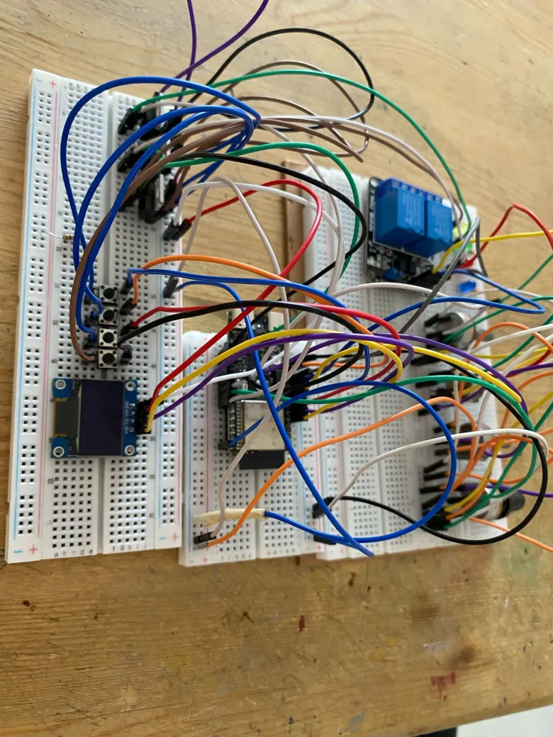
🛠️ HARDWARE DETAILS
🔧 Required Components:
-
ESP32 DevKit v1 (1 unit)
-
IRFZ44N MOSFET (2 units - for red and green LED strips)
-
5V Relay Module (1 unit - room light control)
-
HC-SR04 (1 unit - distance measurement)
-
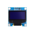
128x64 OLED (I2C) (GPIO6 SDA, GPIO7 SCL)
-
10K Potentiometer (2 units - GPIO4 and GPIO5)
-
Push Button (3 units - GPIO8, GPIO9, GPIO10)
-
10K Resistor (5 units - for pull-up)
-
Breadboard (1 unit)
-
Jumper Wires (20+ units)
🎛️ Pin Mapping:
⚡ Power Management:
-
ESP32: 120mA
-
LED Strip (12V): 2000mA
-
Relay Module: 80mA
-
HC-SR04: 15mA
-
OLED Display: 25mA
💾 SOFTWARE SETUP
📥 Required Libraries:
Core Libraries:
-
Adafruit_GFX (v1.10.12) -
Adafruit_SSD1306 (v2.5.7) -
WiFi (v2.0.0) -
ESPAsyncWebServer (v3.1.0)
Time and Weather:
-
NTPClient (v3.2.1) -
ArduinoJson (v6.19.4) -
HTTPClient (v1.2)
⚙️ Code Structure:
🔄 Flashing Process (Arduino IDE):
-
Tools > Board > ESP32 Dev Module
-
Flash Mode: "QIO"
-
Flash Size: "4MB (32Mb)"
-
Partition Scheme: "Default 4MB"
Custom Settings:
🎛️ SYSTEM FEATURES
💡 LED Control System:
PWM Features:
-
8-bit resolution (0–255)
-
5kHz PWM frequency
Control:
-
POT1: Red LED intensity
-
POT2: Green LED intensity
⏱️ Time-Based System:
-
Timezone: Turkey/Istanbul (GMT+3)
-
Relay activation based on HC-SR04 after 7:00 PM:
-
Person detected: ON
-
No presence: OFF
-
🌤️ Weather Integration:
-
Ankara weather (OpenWeatherMap API):
GET https://api.openweathermap.org/data/2.5/weather?q=Ankara,TR&appid=YOUR_API_KEY&units=metric&lang=en -
BTN3 (double click): Activates dance mode — LEDs synchronize based on weather
🖥️ USER INTERFACE
📺 OLED Menu Structure:
-
Main Menu
-
LED Values → Red: 0–255 / Green: 0–255
-
Relay Status → ON/OFF
-
MOSFET Status → PWM Setting / ON/OFF
-
🕹️ Button Controls:
BTN1:
-
Single Click: Menu Down
-
Double Click: Relay Status
-
Usage: POT1 Value Adjustment
BTN2:
-
Single Click: Menu Up
-
Double Click: MOSFET Status
-
Usage: POT1 Value Adjustment
BTN3:
-
Single Click: Confirm Selection
-
Double Click: Dance Mode
-
Usage: Toggle Options
🌐 Web Interface:
Endpoints:
-
/→ Homepage -
/relay/on→ Turn Relay ON -
/relay/off→ Turn Relay OFF
🔧 TROUBLESHOOTING GUIDE
🚨 Common Issues:
LEDs Not Working:
-
Check MOSFET gate resistor (10K–100Ω)
-
Verify 12V power supply
-
Lower PWM frequency (try 500Hz)
HC-SR04 Inaccurate Readings:
WiFi Connection Problems:
📊 Serial Monitor Test Commands:
-
SYSTEM INFO→ System Information -
LED TEST RED 255→ LED Test -
RELAY TOGGLE→ Relay Test -
SENSOR READ→ Sensor Test
📈 ADVANCED SETTINGS
⚙️ EEPROM Configuration:
-
0x00: WiFi SSID (32 bytes) -
0x20: WiFi Password (64 bytes) -
0x60: LED Settings (16 bytes) -
0x70: Timing (32 bytes)
📜 LICENSE:
-
CERN-OHL-S-2.0
🤝 SPONSORS
📞 CONTACT & SUPPORT
-
Email: info@makerpcb.com.tr
-
Website: https://makerpcb.com.tr
-
Issue Tracking: GitHub Issues
This document covers all project details. For updates, follow the GitHub project page:
🔗 https://github.com/hamzadenizyilmaz/RGB-Control-System-with-ESP32-C6