Story
PWM controller with galvanic isolation
Circuit operation
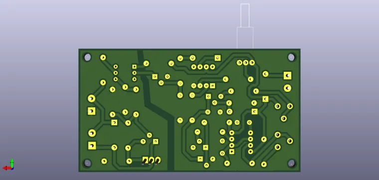
With this type of circuit you can control the speed of a motor from 0 to 100%. The pulses are generated by the oscillator made with NE555, the frequency is adjusted with the RV1 potentiometer. The signal is then picked up by a discharge circuit of the capacitor C3 which is charged through Q3, a constant current generator, at a current controlled by RV2. A ramp-type signal is thus applied to input 2 of the operational, sawtooth, which will be compared with the voltage on the slider of RV3 (Cut-off). This adjusts the filling factor of the rectangular signal generated by U1. The PWM pulses thus generated will be applied to a final stage, a cascade amplifier, through an optocoupler, thus isolating the control part from the force part. The power supplies are separated, the driver stage can be supplied with voltages corresponding to the type of motor used. As can be seen, Q1 and Q2 allow a rapid fall of the decreasing front, a rapid discharge of the C3 capacity, the signal having a "sawtooth" shape with an extremely linear slope. Likewise, the optocoupler transistor allows a quick opening of the Darlington circuit which has additionally arranged the resistors R15 and R16 for a fast discharge of the parasitic capacitances and obtaining excellent fronts even at higher frequencies. It is based on the control in pulses generated by U1, transformed into a sawtooth using the constant current generator made with Q3 and the comparator U2 performs the cut-off related to the voltage on the non-inverting input thus setting the pulse duration.
The signal is then transmitted through the optocoupler to the final stage which will be in charge of the motor. From RV1 the pulse frequency is adjusted, from RV2 the charging current of C3 is adjusted, the slope, and from RV3 the pulse duration is adjusted.
Bill of Materials available in the download section.
Have fun with it !


