


Story
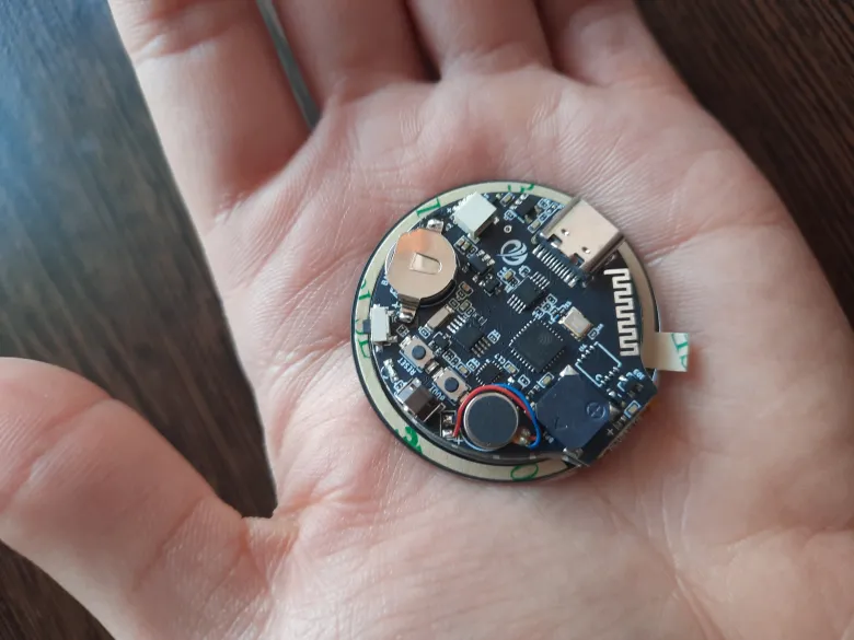
In what follows, I'll show you how I used the Arduino IDE v2.3.4 to upload some test programs to the CrowPanel ESP32 1.28-inch Round Display, so stay tuned, but first a few steps are required.
I assume you have used Arduino IDE before, if not, then google Arduino IDE and download the program.
- Download Arduino IDE from the official website and after you install it, open it and copy this as a text "https://espressif.github.io/arduino-esp32/package_esp32_index.json" to the place indicated in the pictures below.


- Usually, you will see Arduino Uno on the boards, but we don't use that, so we need to look for our board:

Now we can continue and upload a few sketches.
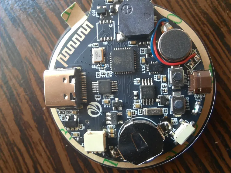
Push button test
The first program tested is one that shows a message in the Serial Monitor when we press the push button on the board:
// Define the pin number for the button
const int buttonPin = 1;  // The pin number where the button is connected

// Variable to store the current state of the button
int buttonState = 0;  // Variable to hold the button's state, initially set to HIGH (0)

void setup() {
  Serial.begin(115200);  // Initialize serial communication at a baud rate of 115200
  pinMode(buttonPin, INPUT);  // Set the button pin as an input
}

void loop() {
  // Read the current state of the button (HIGH or LOW)
  buttonState = digitalRead(buttonPin);

  // If the button is pressed (connected to ground, state is LOW)
  if (buttonState == LOW) {
    Serial.println("Button Press");  // Print a message when the button is pressed
  }
  // If the button is not pressed, it is in the release state (HIGH)
  else {
    Serial.println("Button release");  // Print a message when the button is released
  }

  // Note: This loop will continuously read the button state and print messages.
  // This may not be the desired behavior in all applications.
  // Consider adding a delay or using a debouncing method for the button.
}
And you can find a video on my YouTube channel: https://youtu.be/RAy8XQdcTJ0
Buzzer test
A slightly more "dynamic" program is this one through which the small built-in buzzer is put into operation:
// Define the pin number for the buzzer
#define BUZZER 3

void setup() {
  // This code runs once at the beginning of the program:
  pinMode(BUZZER, OUTPUT);  // Set the buzzer pin as an output
  digitalWrite(BUZZER, LOW);  // Initially set the buzzer to a low state (off)
}

void loop() {
  // This code runs repeatedly after the setup():
  tone(BUZZER, 100);  // Make the buzzer produce a tone at a frequency of 100 Hz
  delay(1000);  // Wait for one second
  tone(BUZZER, 0);  // Stop the buzzer from producing sound (frequency set to 0)
  delay(1000);  // Wait for another second
}
And you can find a video on my YouTube channel: https://youtu.be/oS1XGoXtpOA
To see even more tutorials, I suggest you access the links from the manufacturer of this device:
• https://www.elecrow.com/wiki/CrowPanel_ESP32_1.28-inch_Round_Display.html
• https://www.elecrow.com/wiki/ESP32_1.28-inch_Round_Display_Tutorial.html#tutorial-on-arduino-ide
I have tested almost all the sketches, the procedure is the same, what I have left is the program for the encoder, it is a small component assembled on a PCB and requires a tool like the one for the SIM card in phones, but I don't have a suitable one and I haven't been able to rotate it.
There will be more to come, I'm learning along with you. 🙂
Thank you for reading this blog and have great day!