Add to cart
Board Type : GerberFile :
Layer : Dimensions :
PCB Qty :
Different PCB Design
PCB Thickness : PCB Color :
Surface Finish : Castellated Hole :
Copper Weight : 1 oz Production Time :
Total: US $
Elecrow community is a shared platform and we are not responsible for any design issues.

PCB Assembly

PCBA Qty: BomFile:
NO. OF UNIQUE PARTS: NO. of Components:
Assembly Cost: US $
Elecrow community is a shared platform and we are not responsible for any design issues.
Add to cart
3dPrintingFile : Size :
Unit : Volumn :
3D Printing Qty : Material :
Total: US $12.99
Elecrow community is a shared platform and we are not responsible for any design issues.
Add to cart
Acrylic Type : AcrylicFile :
Dimensions: Engrave:
Acrylic Qty :
Acrylic Thickness:
Acrylic Color:
Total: US $12.99
Elecrow community is a shared platform and we are not responsible for any design issues.
closed
user-img

Cristian Pitigoi

Published: Aug 15,2024

Phone Calling Dectector

ccc ccc
Copyright Info

Attribution-ShareAlike (CC BY-SA)

Read More⇒
  159
  1
  0
cover-img
 
  • thumbnail-img
  • thumbnail-img
  • thumbnail-img
  • thumbnail-img
 

Hardware Components

  • LM358

    X 1 fenxiang
  • BC337

    X 1 fenxiang

Tools, APP Software Used etc.

  • Kicad

Story

Phone Calling Dectector


Circuit operation


This circuit can be used for detecting the signals emitted by our cell phones when we are called or call another user.

When calling a GSM mobile, identification signals (Signal Control) appear, a signal sent to a cell phone from a base station or vice versa, from the cell phone to the station. It contains essential information for the call, but does not include the audio portion of the conversation. Access by Multiple Code Division, also called Spread Spectrum, CDMA cellular systems use a single frequency band for all traffic, differentiating individual transmissions by assigning them unique codes before transmission.

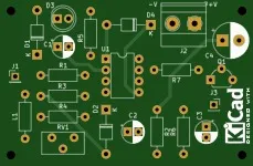
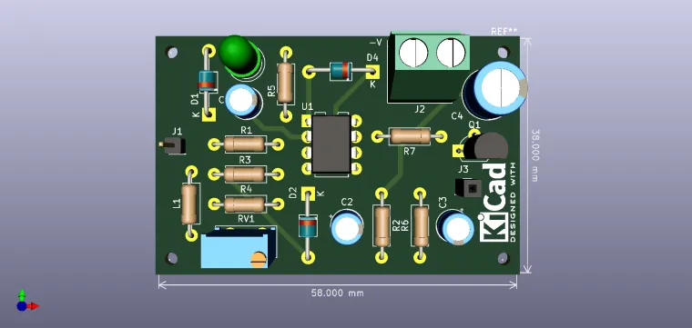
There are a lot of CDMA variants (W-CDMA, BCDMA, TD-SCDMA). Detection is performed with Schottky diodes and the level is adjustable. The signal is applied to the first stage as a comparator at the output of which the signal is integrated to maintain for several seconds the voltage level at a value sufficient to be amplified by U1B and opens the transistor Q1. The setting is made from RV1 to a value that allows the LED D3 to light at a maximum intensity. An antenna of approx. 10 cm (adjust the length for maximum gain).


Bill of materials available in the download section.

Enjoy it!

Schematic and Layout
user-img

Cristian Pitigoi

+ Follow

Topic

View All
phone
  • Comments( 0 )
  • Like( 1 )
/1000
Upload a photo:
You can only upload 1 files in total. Each file cannot exceed 2MB. Supports JPG, JPEG, GIF, PNG, BMP

You May Also Like

View All