Story
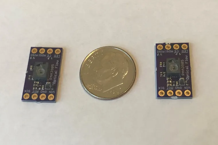
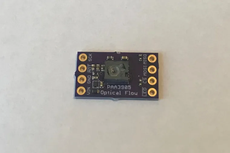
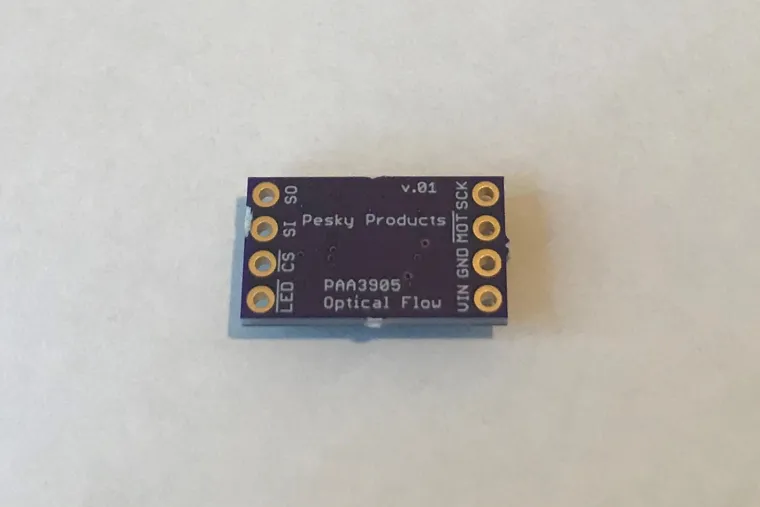
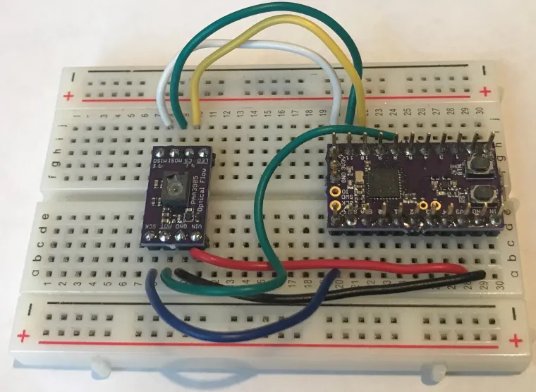
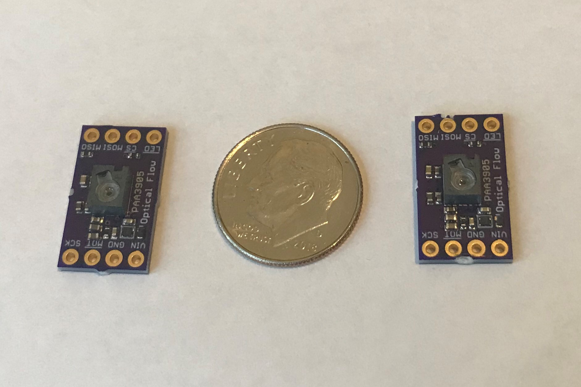
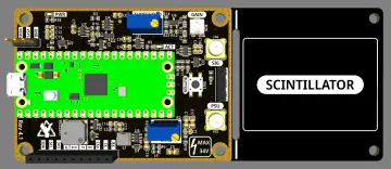
This is a small (17.9 mm x 10.3 mm) breakout board for PixArt's PAA3905 optical flow sensor.
From the data sheet: "The PAA3905E1 is PixArt Imaging's optical motion tracking chip specifically designed for low light level operation. ... It is suitable for far field tracking application in providing motion tracking with stable hovering function for drone."
In other words, the sensor provides lateral velocity information useful for UAV hovering and navigation. It's 80 mm minimum distance also allows application to navigation of rolling robots within the limitation of its maximum 7.2 rad/s flow speed.
The sensor uses an 8-bit, 35 x 35 pixel imager which is sensitive to both visible and infrared (940 nm) light. The sensor automatically identifies features in the pixel map and tracks them from frame to frame at up to 126 Hz frame rate to identify the average feature motion, which is reported as signed 16-bit delta X and delta Y, proportional to the lateral velocity components. The proportionality depends on the distance from the sensor to the measurement surface as well as the resolution set by the user. In general, user calibration of speed vs output counts at the working distance is recommended for best results.
The sensor comes with a properly fitted L242-ZSZ1 polycarbonate lens made specifically for the PAA3905 IC but gluing this lens to the PAA3905 liquid crystal polymer package is left up to the user. Gluing is recommended where significant mechanical impact during use is expected. Bonding agents such as LOCTITE 3129, EPOTEK 730, or UV curable adhesive can be used among others. Contact PixArt for details.
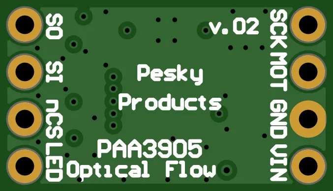
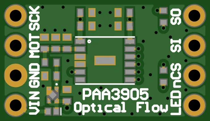
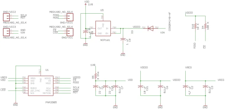
The sensor uses standard SPI for communications (nCS, MOSI, MISO, SCLK exposed on the breakout) at a maximum serial port speed of 2 MHz. The sensor has an interrupt for data ready (active LOW) exposed on the breakout. Power input is limited to 1.8 - 3.6 V and GND. Lastly, there is an led sync pin (active LOW) exposed on the board for controlling an led via a FET (not included with the breakout) for custom illumination. Given the sensitivity of the image sensor to the IR, a 940 nm led would be a good choice.
Multiple PAA3905 sensors can be synced together to match data timing or one or more PAA3905 can be synced with other sensors such as IMUs, etc. For both led and sensor sync functionality contact PixArt for more details.
The sensor uses typically 3.5 mA in operation and has a 12 uA shutdown mode
This sensor offers two sensitivities: standard detection and enhanced detection for rough terrain at > 15 cm height. The sensor can automatically switch between bright (>60 lux), low light (>30 lux), and super low light (> 5 lux) conditions (perfect for dusk or overcast operation). Bright and low light modes work at 126 frames per second. The super low light mode is limited to 50 frames per second.
The sensor can operate in navigate mode producing delta X and Y values which are proportional to lateral velocity. The limiting speed is determined by the maximum 7.2 rads/sec flow rate and by the distance to the measurement surface; 80 mm is the minimum measurement distance. So at 80 mm the maximum speed is 0.58 m/s (1.3 mph), at 2 meter distance (~drone height) the maximum speed is 14.4 m/s (32 mph), etc.
The x and y values output from the sensor are raw flow rate in signed int16_t format. So the proper scale is to multiply these values by 7.2 / 32768 to get flow rate in units of rads/sec at the minimum 80 mm distance. Multiply by height/80 mm for larger distances.
You can also just calibrate by integrating the raw flow rate to get travel over a known distance to be sure.
If mounted on a rolling robot make sure the distance to the ground is at least 80 mm for best results.
The sensor can also operate in raw data (frame grab) mode producing 35 x 35 pixel images from the sensor at a frame rate of ~18 Hz. This makes the PAA3905 an inexpensive, low-resolution, infrared-sensitive video camera. The data sheet cautions: "the sensor needs to be held stationary for the duration of grabbing raw data until the data array is completely read out". I measured the complete frame grabbing process to take 56 milliseconds. The stationary requirement is to presumably avoid blurring; changing of the pixel values during the readout process. So it remains to be demonstrated how accurate of a "video camera" this sensor can be.
I tested this using Adafruit's 160 x 128 pixel rgb TFT display on an STM32L476 Dragonfly development board.
In the main loop it takes 56 ms to grab a 35 x 35 pixel (each pixel is 1 byte) frame but the display rate seems more like about ~2 Hz or so.
I am plotting the data on the TFT display by mapping rgb colors to intensity. Since I am using the Dragonfly with its embedded 16 MByte SPI NOR flash I could also just store the 1225 bytes of data per frame on the flash for later download. I could record ~10 minutes of video at the ~18 Hz frame rate.
In the image below the PAA3905 is pointed toward a window with my hand in the field of view (basically backlit). In addition to faster display speed, using the PAA3905 as a video camera would benefit from using an IR (830 or 940 nm) led and the led sync pin for scene illumination.

Here is another video demo of the PAA3905 in video mode taken by Simon Levy.
There are Arduino sketches reposited at Github (see also here) that configure the sensor parameters, set up the data ready interrupt, and output both navigation data and 35 x 35 pixel raw data frames. The sketches demonstrates most of the operations of the sensor and are a good basis for customizing to your application.


