


Story
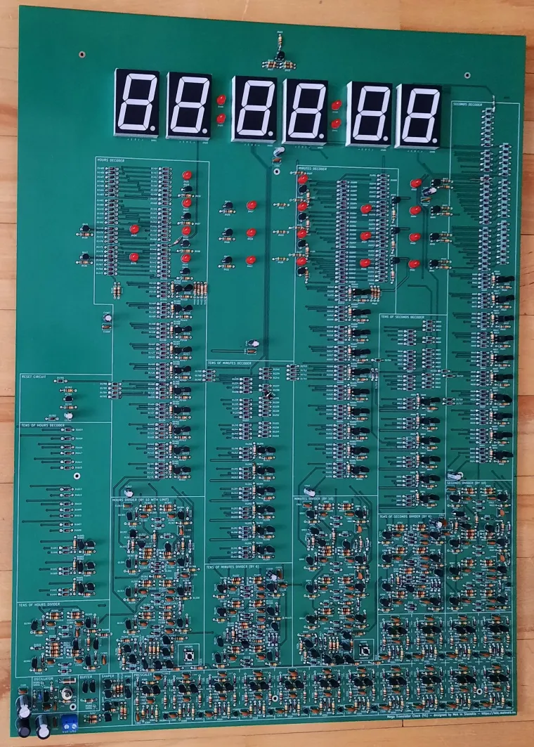
This clock does not contain any integrated circuits and is designed by myself. All parts are common and easily obtainable. Also older parts pulled from old devices can find their place here if they are OK.
This construction is intended for medium-advanced electronics enthusiasts who already know how to solder, and can identify parts, their parameters and polarity.
It will surely draw attention of your visitors and will be a nice accessory of the room.
Parameters
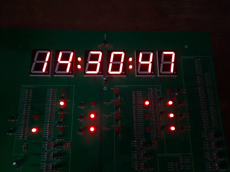
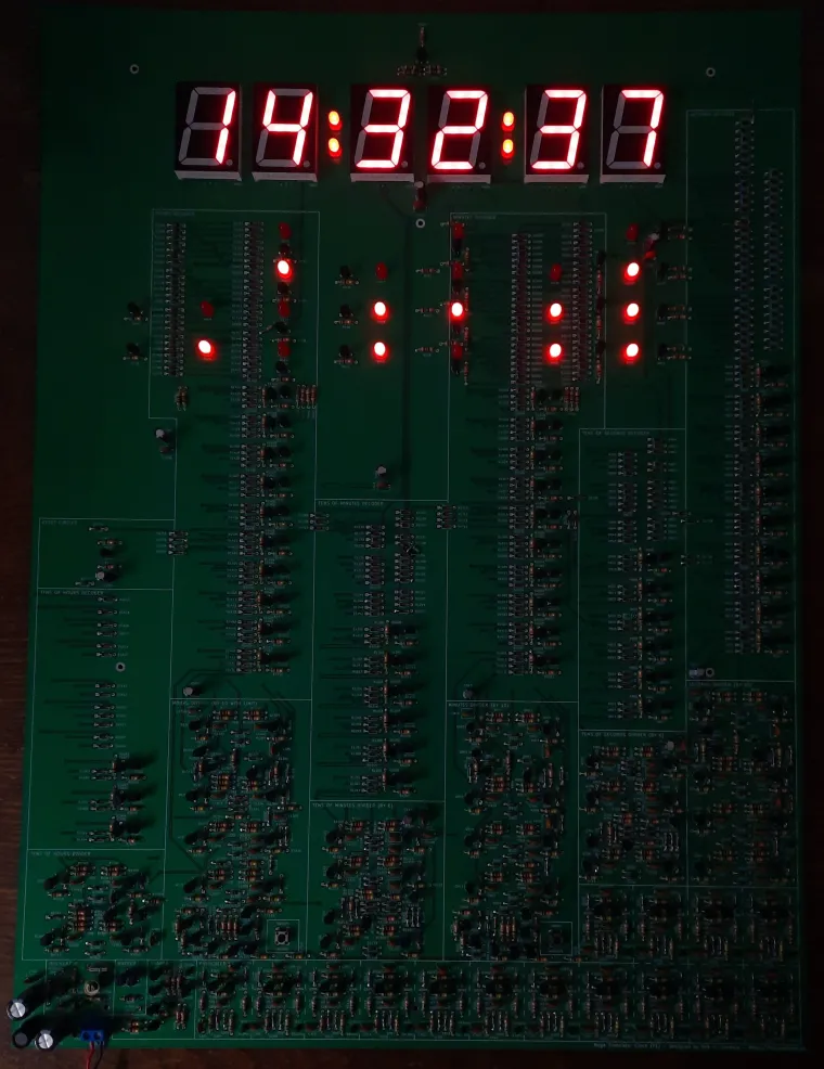
- Digital and binary time representation
- 24-hour time format, blinking double dots (colons)
- 2 push buttons for time setup (hours and minutes)
- Crystal resonator as time base
- Power supply: 5 V / 500 mA max.
- 596 diodes and 221 transistors
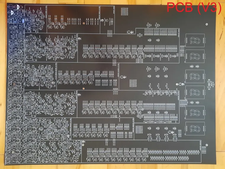
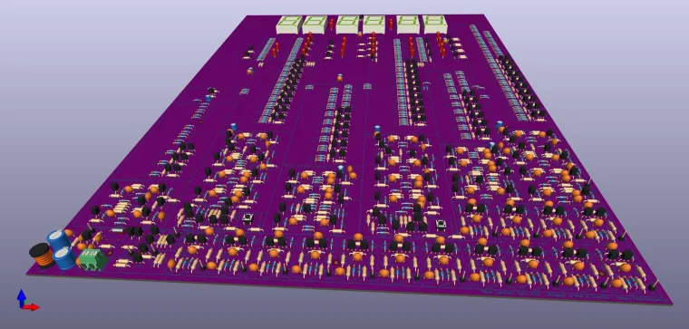
- PCB dimensions: 50 x 37 cm (V1) or 48.5 x 37 cm (V3) - height x width
Interactive part list is in file BOM.html and as a picture in Top.png. All files are available for download at my web page. Not everything could be published here on Elecrow because of file size limits.
Circuit description
Detailed description, including the schematic, is in the documentation for download. The following is a block schematic (click to enlarge):
![]()
The sections are named the same as on the PCB - they are also highlighted on the PCB for easier orientation.
The oscillator is driven by a watch crystal of frequency 32.768 kHz, its output is similar to sine wave, but with some offset and unsuitable peak-to-peak levels. For further processing, it must be converted into logic levels (square wave 0 - 5 V) and that is the job of the Buffer and Shaper sections.
Following flip-flops divide the 32.768 kHz by two as many times as needed in order to obtain a 1 Hz signal that is used to count seconds.
Divider by 10 counts seconds, divider by 6 counts tens of seconds. Flip-flop outputs are connected to LEDs for binary time representation, and also to decoders. The decoders determine which segments of the display will light up in which state of the flip-flops.
Same goes for the sections to count minutes, but with a little difference - the push button for setup of minutes. When the button is pressed, minutes are clocked by a 2 Hz signal, otherwise they are clocked from the output of tens of seconds divider.
The sections to count hours and tens of hours are interconnected in such a way that they count from 0 to 23. Again, there is a push button to set up the hours, that works the same way as for minutes.
Reset circuit is also present so that the clock starts from 00:00:00 and not some random state.
Dividers by 6, 10, and 24, are in fact sequential logic circuits formed from flip-flops and logic gates made only from transistors and diodes. The following pictures are from a program called Logisim - a simulator of logic circuits.
![]() Divider by 10
Divider by 10
![]()
Divider by 6
![]()
Divider by 24
The following are logic gates consisting of transistors and diodes:
![]()
Flip-flop
![]()
AND gate
![]()
OR gate - both types are used in this construction
All detailed information about the circuit, recommended order of steps to finish the construction, and various good advices, are in the documentation for download at my web page.
Because of huge effort needed to design this clock, the PCB design is not public (but the schematic is, as it is important to debug the circuit and show how it works).
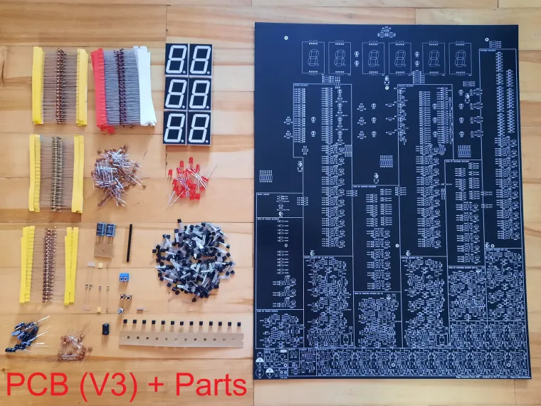
BOM in short:
- NPN transistors (208 pcs)
- PNP transistors (13 pcs)
- diodes 1N4148 (596 pcs)
- electrolytic capacitors 10 μF / 16 V (10 pcs)
- electrolytic capacitors 1000 μF / 16 V (2 pcs)
- ceramic capacitors 100 pF (105 pcs)
- ceramic capacitors 22 pF (2 pcs)
- ceramic capacitors 100 nF (12 pcs)
- ceramic capacitors 22 nF (2 pcs)
- ceramic capacitor 1 nF
- resistors 150 Ω (66 pcs)
- resistors 1 kΩ (74 pcs)
- resistors 100 kΩ (144 pcs)
- resistors 10 kΩ (165 pcs)
- resistors 1 MΩ (2 pcs)
- resistor 10 MΩ
- resistor 470 kΩ
- crystal resonator 32.768 kHz
- display 38.1 mm (1.5 in) red (6 pcs)
- LED diodes 5 mm red 20 mcd (24 pcs)
- radial choke 120 μH or similar
- push buttons 6 mm for PCB (2 pcs)
- pin header 1x20, pin spacing 2,54 mm
- capacitor trimmer
- 2-lead PCB screw terminal block
This kit can be bought directly from the author or at various marketplaces while stock lasts.