


Story
Overview
The 8-Channel RC Transmitter and Receiver System is crafted for RC enthusiasts and hobbyists who want a reliable, high-performance, and customizable remote control system. Designed around the powerful STM32F103C8T6 microcontroller and the robust NRF24L01 wireless communication module, this system ensures long-range connectivity, stable signal transmission, and seamless integration with RC vehicles, aircraft, and simulators.
Features
| Transmitter (TX) | Feature | Description |
|---|---|---|
| User Interface Initialization | STM32F103C8T6 microcontroller powers up, activating a 0.96" OLED display to showcase a user-friendly menu system for easy navigation and configuration. | |
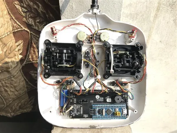
| Control Inputs Processing | Dual potentiometers and switches capture user commands, enabling adjustments like stick calibration, channel tuning, and mode selection. | |
| Data Encoding & Transmission | Microcontroller encodes inputs into a data packet, which the NRF24L01 wireless module transmits to the receiver. | |
| PPM Output for Simulator | In simulator mode, generates PPM signal for simulators, creating a realistic RC training environment. | |
| Audio Feedback with Buzzer | Microcontroller triggers buzzer for feedback, warnings, or successful commands, enriching user experience. | |
| Customizable Channel Configuration | Menu allows configuration of individual channels (inversion, tuning), with settings stored for precise control over devices. |
| Receiver (RX) | Feature | Description |
|---|---|---|
| Data Reception | Wireless Reception | NRF24L01 module scans for incoming data packets, forwarding them to STM32F103C8T6 for processing. |
| Data Decoding & Channel Output | Decodes data packets, extracting transmitter inputs and configurations to generate PWM, PPM, or SBus signals. | |
| Signal Output | Output Signal Options | Supports 8-channel PWM for direct servo control, PPM for consolidated control, and SBus for efficient serial communication. |
| Smooth Operation & Control | Outputs precise signals to connected devices, ensuring responsive and smooth control over RC vehicles, drones, and other equipment. |
Technical Specifications
| Specification | Transmitter | Receiver |
|---|---|---|
| Microcontroller | STM32F103C8T6 (32-bit ARM Cortex-M3) | STM32F103C8T6 (32-bit ARM Cortex-M3) |
| Wireless Communication | NRF24L01 GT24 Mini (2.4GHz) | NRF24L01 GT24 Mini (2.4GHz) |
| Display | 0.96-inch OLED, 128x64 pixels | Not Applicable |
| Input Voltage | 5V DC | 5V DC |
| Output Signals | PPM signal output for simulators | 8-channel PWM, PPM, SBUS |
| Current Consumption | ~50mA (average, transmitter only) | ~30mA (average) |
| Battery Requirement | 7.4V LiPo battery (transmitter) | Power via USB or external power supply |
| Transmission Range | 1-1.5 km (in open field, line of sight) | Matches transmitter range |
| Supported Channels | 8 channels | 8 channels |
| Signal Latency | Less than 20ms | Less than 20ms |
| Calibration Options | Trim adjustment, stick calibration | Not Applicable |
| Control Inputs | Dual potentiometers, dual switches, rotary encoder | Not Applicable |
| User Interface | OLED display with menu options | Not Applicable |
| Protection Features | Overcurrent protection on regulator (AMS1117) | Overcurrent protection on regulator (AMS1117) |
| Voltage Regulator | AMS1117 (3.3V output) | AMS1117 (3.3V output) |
| Audio Feedback | Buzzer for alerts and status | Not Applicable |
| Component Size | Compact design with SMD components | Compact design with SMD components |
| Programming Interface | USB to serial converter (CH340) | USB to serial converter (CH340) |
| Firmware Upload Time | Approx. 15 seconds per upload | Approx. 15 seconds per upload |
| Binding Process | Automatic pairing with receiver | Automatic pairing with transmitter |
| Operating Temperature | -20°C to +60°C | -20°C to +60°C |
| Signal Compatibility | Compatible with FPV simulators, PC apps | Compatible with RC cars, drones, aircraft |
| Dimensions | Small custom PCB, compact for enclosure fitment | Small custom PCB, easily mountable |
| Weight | Lightweight (depends on case) | Lightweight, easy to integrate |
| Firmware Update Method | Via USB serial connection | Via USB serial connection |
Required Components
Transmitter Components
| Component | Description | Quantity | Link |
|---|---|---|---|
| STM32F103C8T6 | Microcontroller for processing signals | 1 | Click to Buy |
| NRF24L01 GT24 Mini | Wireless module for remote signal transmission | 1 | Click to Buy |
| 0.96-inch OLED | Display for user interface | 1 | Click to Buy |
| 10k Resistor (SMD) | Signal conditioning | 10 | Click to Buy |
| 1k Resistor (SMD) | Signal conditioning | 1 | Click to Buy |
| 100nF Capacitor (SMD) | Decoupling capacitor | 20 | Click to Buy |
| Buzzer | Audio feedback | 1 | Click to Buy |
| SS8050/BC547 | Transistor for power switching | 1 | Click to Buy |
| AMS117 | Voltage regulator (3.3V) | 1 | Click to Buy |
| 10uF Capacitor | Smoothing capacitor for stable voltage | 1 | Click to Buy |
| Male Headers | Connectivity for modular assembly | As needed | Click to Buy |
Receiver Components
| Component | Description | Quantity | Link |
|---|---|---|---|
| STM32F103C8T6 | Microcontroller for receiver signal processing | 1 | Click to Buy |
| NRF24L01 GT24 Mini | Wireless module for remote signal reception | 1 | Click to Buy |
| AMS117 | Voltage regulator (3.3V) | 1 | Click to Buy |
| 10uF Capacitor | Decoupling capacitor for stability | 1 | Click to Buy |
| 100nF Capacitor (SMD) | Smoothing capacitor for stable output signals | 20 | Click to Buy |
| Male Headers | For easy connectivity and prototyping | As needed | Click to Buy |
SCHEMATICS
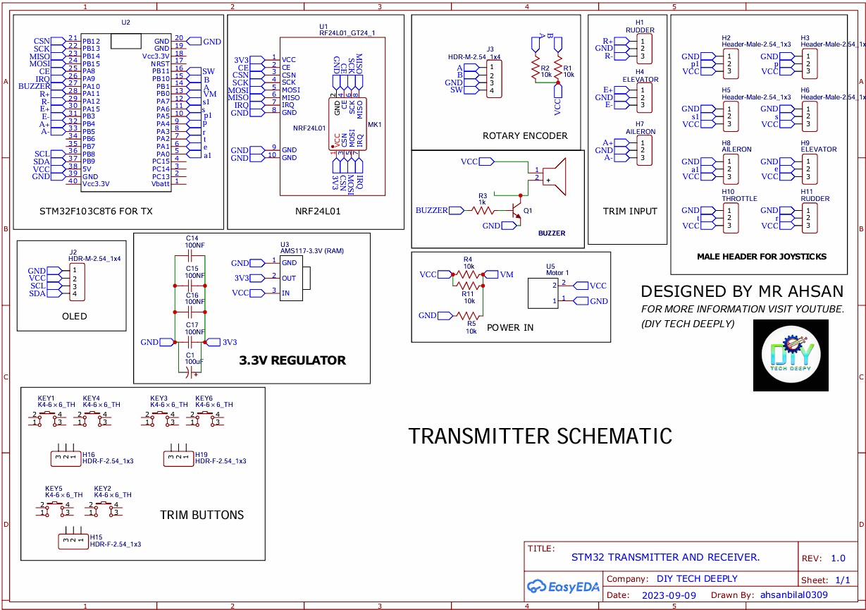
- Transmitter Schematic
A detailed schematic for the transmitter, showing component placement, connectivity, and signal flow.
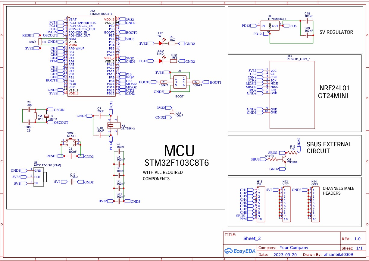
- Receiver
A comprehensive receiver schematic with clear instructions on component layout and signal paths.
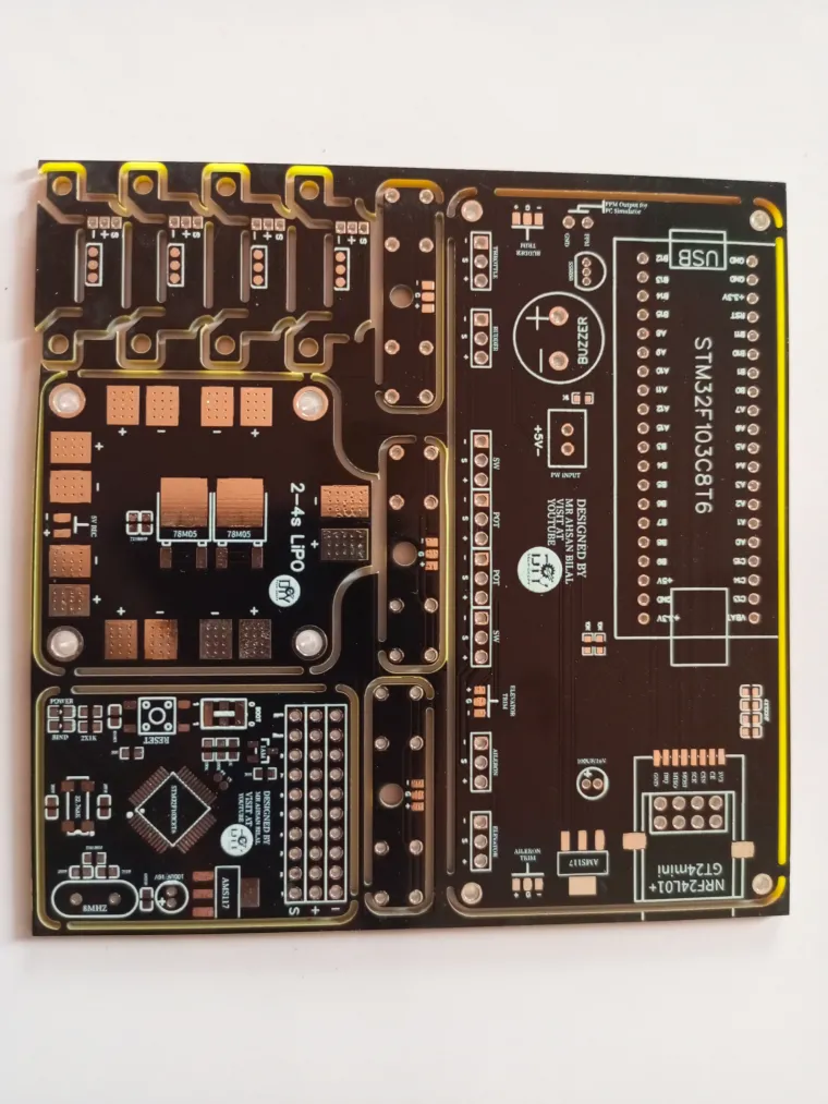
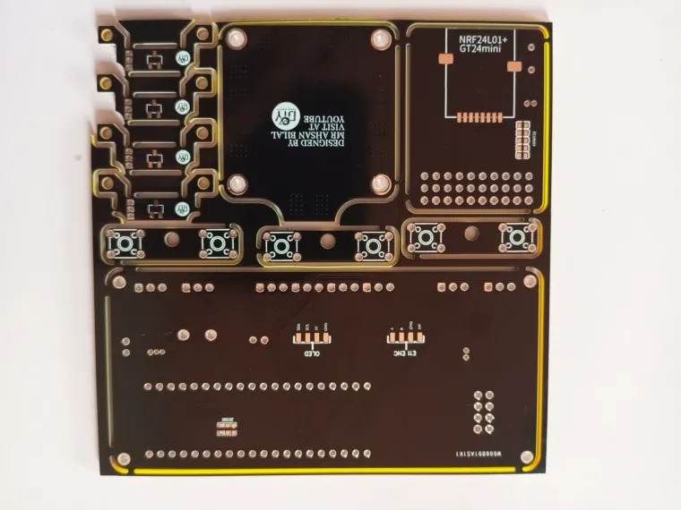
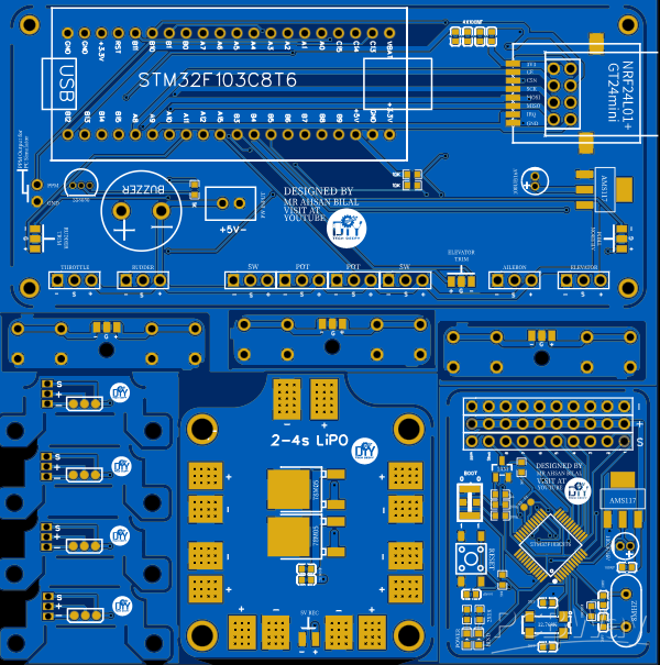
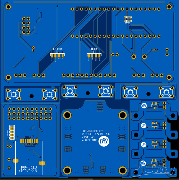
PCB Layout
Firmware Uploading Guide
To upload firmware to the transmitter and receiver, follow these steps:
- Required Tools:
- A USB to Serial Converter such as the CH340 is required to connect to the PC.
- Connection Instructions:
- Transmitter: Connect the USB serial converter to the transmitter’s programming port as per the schematic.

- Receiver: Similarly, connect the converter to the receiver board following the schematic

Firmware Uploading Steps:
Software Download:
Download and install the STMicroelectronics Flash Loader Demonstrator software: Software Link
Upload Process:
- Plug in the USB serial converter and power up the board.
- Press the reset button on the STM32 board to initiate the upload mode.
- In the software, select the correct COM port, click ‘Next’, and proceed to erase any existing firmware.
- Once erased, select ‘Download to Device’ and locate the HEX file for this project.
- Click Upload; the firmware will be uploaded within approximately 15 seconds.
Binding Procedure
To ensure a stable connection between the transmitter and receiver, follow these steps:
- Power On Both Devices:
- Turn on the transmitter and receiver.
- Press Receiver Reset Button:
- Press the reset button on the receiver, triggering the automatic binding process.
- Once bound, the receiver and transmitter will sync seamlessly without interference.
Join DIY TECHOS: Innovate Your Remote Control Experience!
To stay connected with the latest RC innovations, DIY projects, and electronics tutorials, subscribe to DIY TECHOS. Follow us for more updates, and let’s explore the world of DIY RC together.