Story
The project is very variable with many possible modifications.
To begin with, I will describe only the simplest one:
Basic 1 :
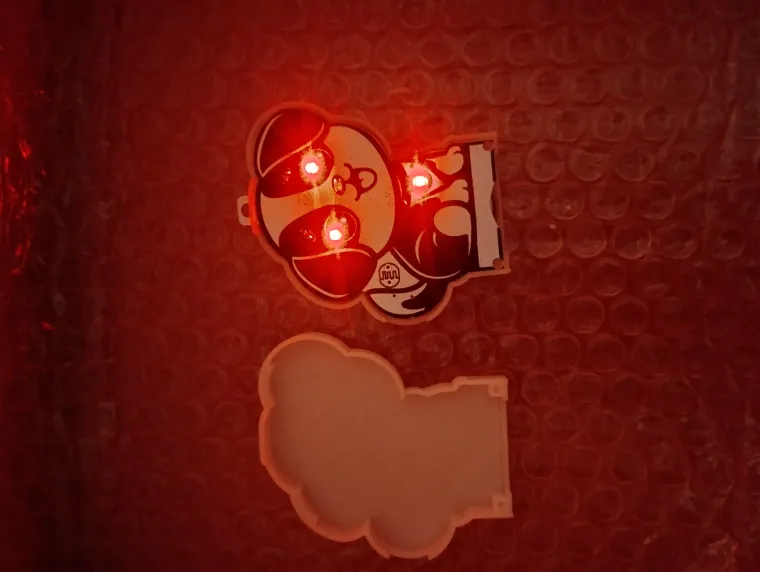
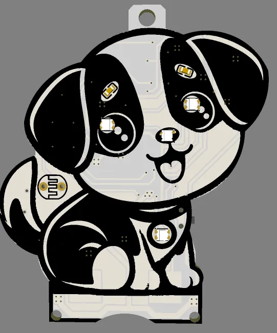
- LEDs, two touch buttons, USB power, CR2032 / LIR2032.
BT1 BAT-SMD_CR2032 1
TTP1,TTP2 TTP223-BA6 touch pad detector IC 2
USB1 U-F-M5SS-W-5 MICRO-USB-SMD_MICRO-USB-A9 1
F1 SMD0805 Fuse OR R0805 0R 1
SW1 MSK-12C02-1_5H 1
U1 CH32V003J4M6 SOP-8 1
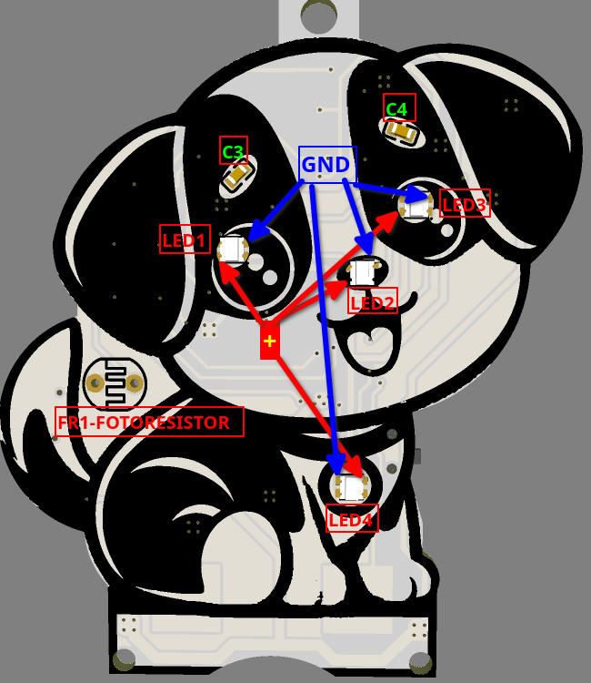
LED1-LED4 WS2812B-2020 RGB LED 4
CT1,CT2 C0603 0-50pF SEE TTP223-BA6 Datasheet(page 4) 2
C2-C4 C0603 100nF 3
C1 C1206 4.7uF 1
RL1 0603 100R 1
PAD-JUMPER-2- 2
JU1,JQ2 SOLDER SMD-SOLDER
To Program the MCU using USB you need to solder DIO jumper ( pic1).
H1, H2 connectors are designed to connect an external module with another MCU( CH32x033...).

SW1 function:
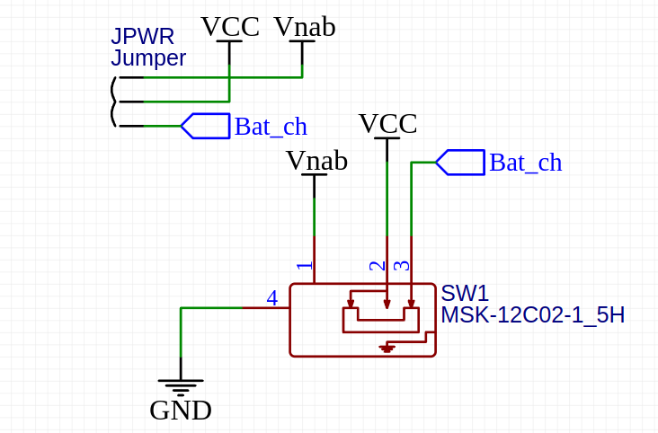
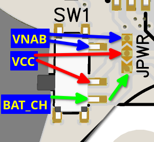
Vnab- power from USB.
Bat_ch- power from Battery.
Touchpoint:
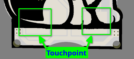
Right touchpoint -TTP1
Left touchpoint -TTP2
CH32V003J4M6 PINS:
PIN I/O FUNCTION
1 OUTPUT -LED DATA
2 POWER GND
3 OUTPUT- LED POWER ON/OFF
4 POWER -VDD
5 INPUT- TOUCHPOINT1
6 INPUT -TOUCHPOINT2
7 OUTPUT -BATTERY POWER ON/OFF
8 INPUT/ AD -DIO/ FOTORESISTOR


