Holiday Notice: Elecrow will be on holiday starting January 26th (GMT+8). the last shipment day for service orders is January 21st. Orders can still be placed during the holiday, but deliveries will be delayed. [Learn More]
Topics
View All
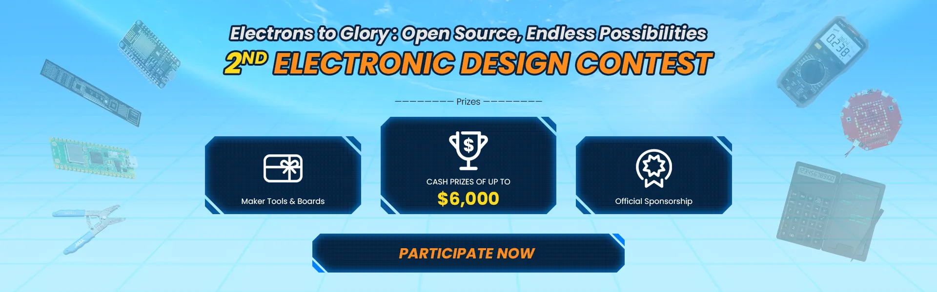
2nd Electronics Design Contest
PCB

DIY Electronics

Arduino

ESP
PCB Assembly

LoRa
Raspberry Pi
3D Printing

Machine Learning & AI

IoT

Acrylic Cutting

Display

Keyboards

Lights

Gaming

Boards & Shields

Health & Medical Devices

Kits

Power Supply

Automotive

CNC

Biometric

Robotics

Prototyping & Fabrication

Actuators

Sensors

Camera

Security

Wearables

Music

Christmas Contest
We Recommend
What kind of projects would we recommend?
- Great Content: e.g. Introduction / Features / Tutorials / Videos
- Complete Files: e.g. Gerber / Bom / Circuit / Schematic / CAD
- Profound Concepts: e.g. Innovative / Practical / Social contribution
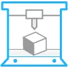
Bored of the classic clock? Check out this one!
 Floppy Lab
Floppy Lab
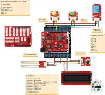
Project #15: Environment – DHT11 – Mk24
 Luc Paquin
Luc Paquin
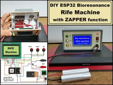
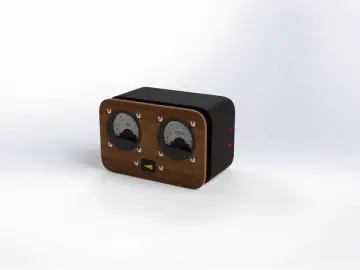
DIY ESP32 Bioresonance Rife Machine with ZAPPER function
 Mirko Pavleski
Mirko Pavleski
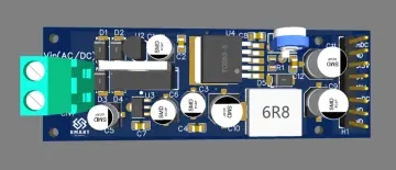
Low Power Universal DC Power Supply Board
Smart Samaan
Most Popular
View All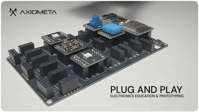
G E N E S I S - Modular Electronics for Innovators
 Povilas Dumcius
Povilas Dumcius
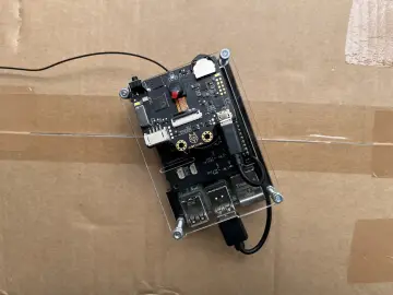
FarmGuard : Farm Security with Cellular IoT and AI
 Samith TM
Samith TM

MAKE 8CH RC TRANSMITTER AND RECEIVER USING STM32 AND NRF24L01
 DIY TECHOS
DIY TECHOS

Cosmic Ray Muon Detector
 Robert Hart
Robert Hart
Latest
View AllProject #15: Environment – DHT11 – Mk24
Luc Paquin
Luc Paquin
DIY ESP32 Bioresonance Rife Machine with ZAPPER function
Mirko Pavleski
Mirko Pavleski
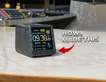
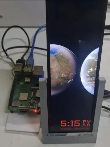
Portable Mini Weather Station: Real-Time Weather Updates wit
DIY TECHOS
DIY TECHOS
Low Power Universal DC Power Supply Board
Smart Samaan
Bored of the classic clock? Check out this one!
Floppy Lab
Floppy Lab
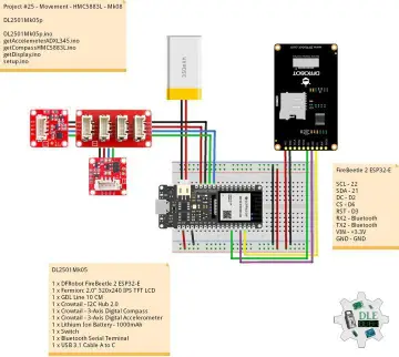
Project #25 - Movement - HMC5883L - Mk08
Luc Paquin
Luc Paquin
Video Tutorials
View All

1 Minute Guide to Learn How Servo Motor Works
How to Build a DIY Solar Tracker using Crowtail
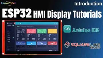
CrowPanel ESP32 Display Tutorials

Elecrow PCB Manufacturing and Assembly Process
Blogs
View All
Elecrow Project Commercialization Model – A New Way to Share, Learn, and Earn!
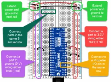
Learn how to use a breadboard in minutes

Unlocking Breakout Boards: Exploring Their Functions and Benefits

What Is The Difference Between Mechanical Keyboard And Normal Keyboard?

Share and explore more open source hardware projects!