


Story
Specifications:
Microcontroller: ATmega328P
Operating Voltage: 5V
Input Voltage (recommended): 7-12V
In/out Voltage (limit): 6-20V
Digital I/O Pins: 14 (of which 6 provide PWM output)
PWM Digital I/O Pins: 6
Analog Input Pins: 6
DC Current per I/O Pin: 20 mA
DC current for 3.3V Pin: 50 mA
Flash Memory: 32 KB (ATmega328P) of which 0.5 KB used by bootloader
SRAM: 2 KB (ATmega328P)
EEPROM: 1 KB (ATmega328P)
Clock Speed: 16 MHz
LED_BUILTIN: 13
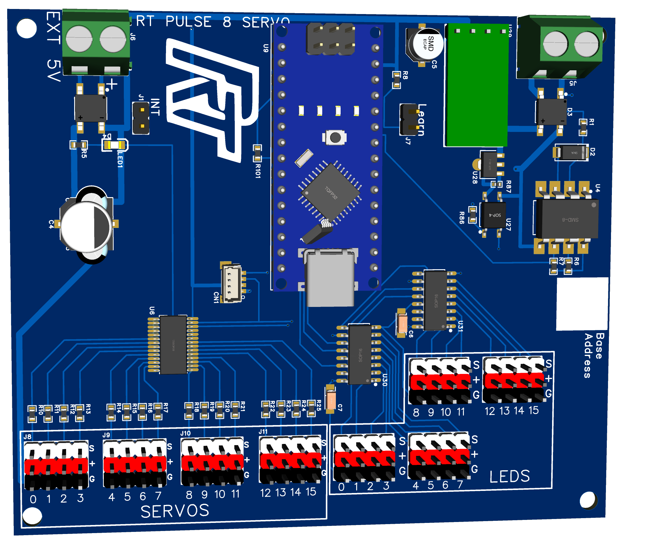
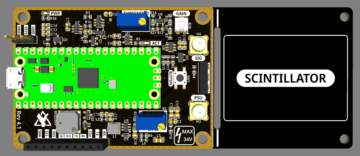
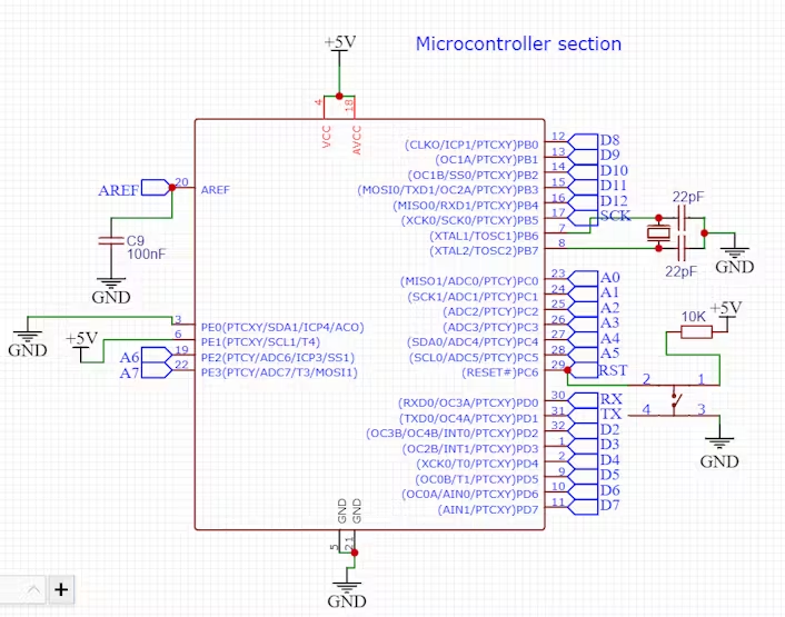
PCB circuit design
Assembly parts list
1) AtMega328p (DIP version)
2) CH340G Usb to TTL (For programming)
3)Micro USB socket
4) 100nF (104) capacitor
5) 22pf capacitor
6) 12Mhz crystal
7) 16Mhz crystal
8) 220-ohm resistor
9) 1k resistor
10) 10k resistor
11) 603 smd led white
12) Pin headers
13) Ams1117 3.3volt
14) Ams1117 5volt
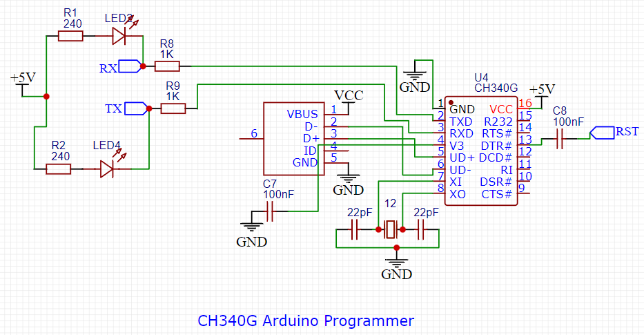
We can try to use the ch340 programmer chip, which is directly connected to USB and is called a USB to serial port chip.
The RX and TX pins are connected to the MCU through 1k resistors and the DTR pin is reset through a 100nf capacitor.
To provide a proper clock signal to the MCU, a 16MHz crystal oscillator and two 22pf ceramic capacitors are required.
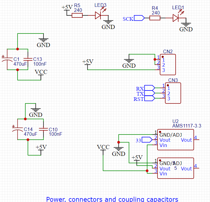
The Ch340 also requires a 12Mhz clock, so there is a separate 12MHz crystal. AMS1117 5v provides 5v to all circuits.
Ch340g is used to provide 3.3v or we can use a separate voltage regulator.
The reset pin is connected to 5v through a 10k resistor and pulled down when we need to reset the programmer.
Some capacitors are used to reduce noise in the signal and there are 4 indicator LEDs for RX, TX, Power and D13.
Programming
Download and install the ch340 programming program,
Upload this flash code for confirmation.
*/

// 当您按下重置或为开发板通电时,设置函数会运行一次
void  setup () {
   // 将数字引脚 LED_BUILTIN 初始化为输出。
  pinMode(LED_BUILTIN, 输出);
}

// 循环函数永远一遍又一遍地运行
void  Loop () {
  digitalWrite(LED_BUILTIN, 高);    // 打开 LED(高电平)
  delay( 1000 );                        // 等待第二次
  digitalWrite(LED_BUILTIN, LOW);     // 通过使电压为低延迟来关闭 LED
  ( 1000 );                        // 稍等一下
}