
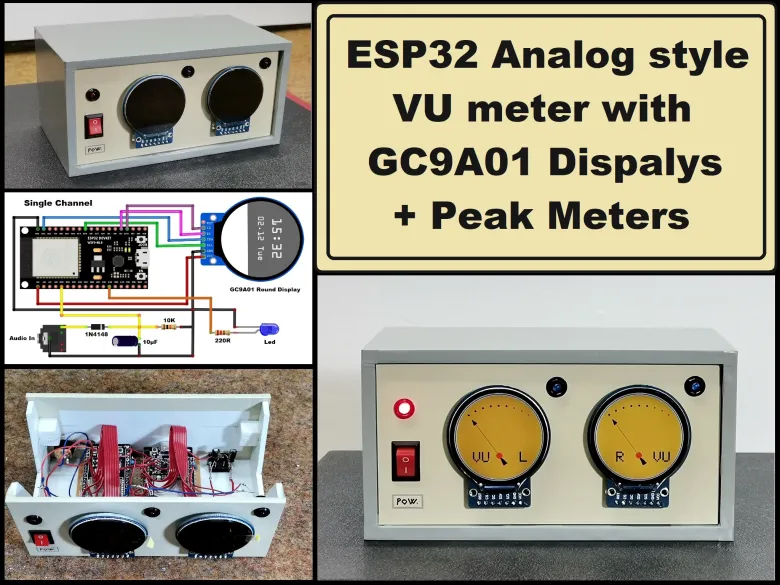
Story
A typical VU meter measures audio signals and displays them with a visual indicator. In the classic VU meter design is used a moving needle (actually a sensitive galvanometer) that points to a scale on a calibrated range.
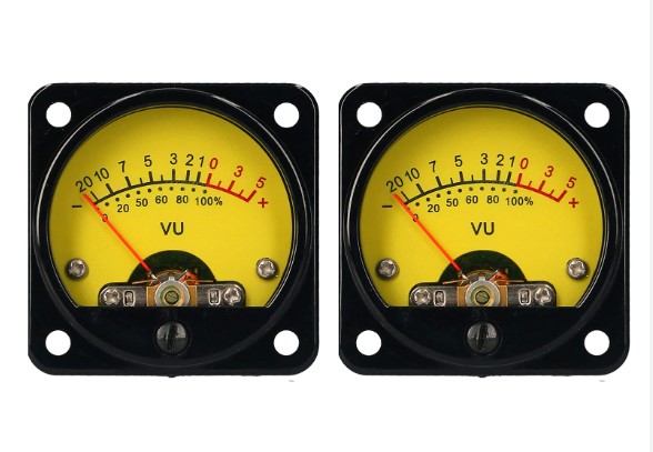
The needle moves left or right depending on the strength of the audio signal. I recently acquired these small round TFT displays with a GC9A01 chip. Its basic purpose is for making smart watches, but in fact their shape is ideally suited for making a retro-look VU meter. My attention was drawn to a project on thesolaruniverse blog, which describes in detail how to create meters gauges and dials on this display with arduino nano.
Detailed video description at: https://youtu.be/kKqEtkJZw0g
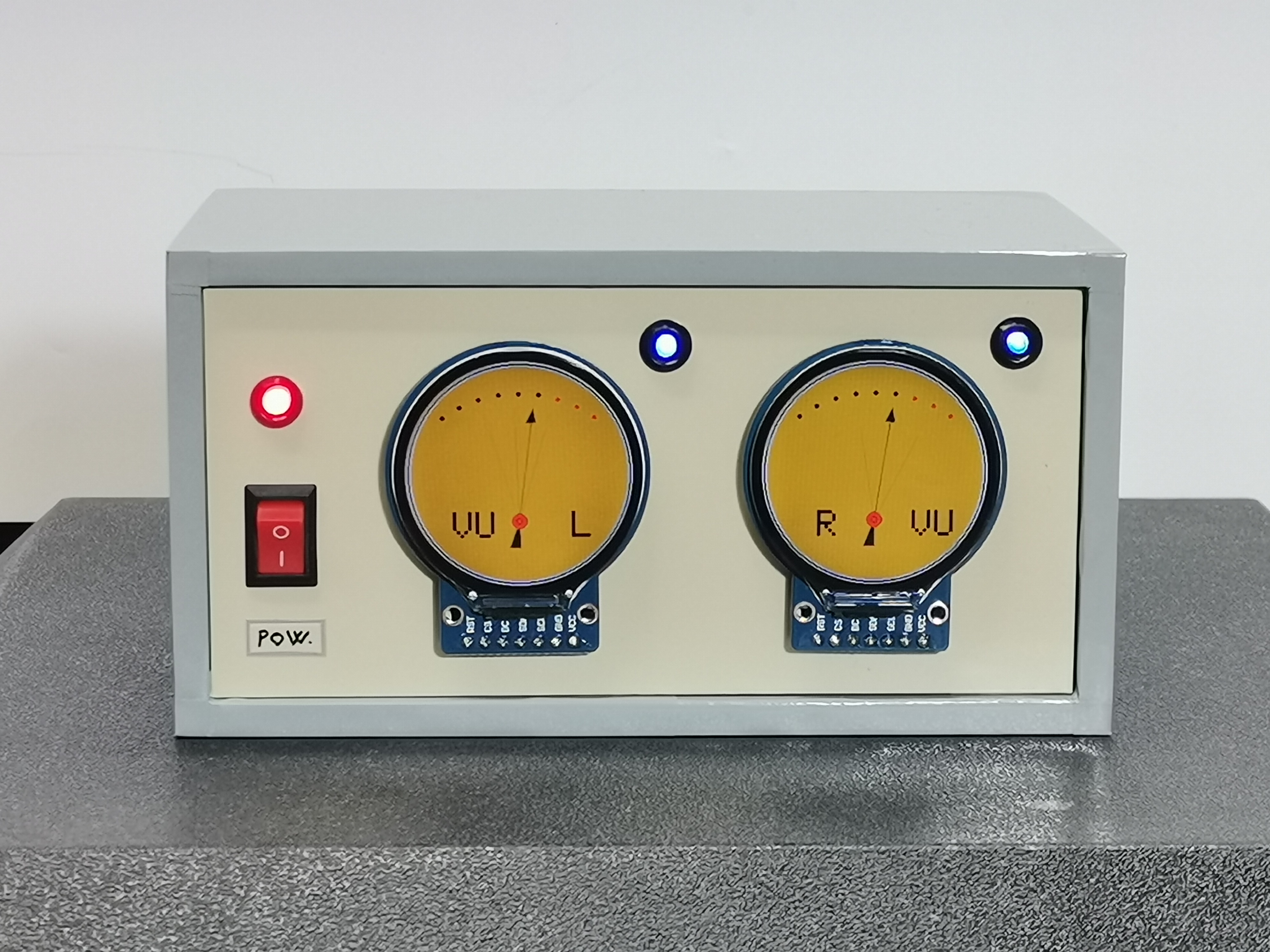
For the needs of this project I made some modifications to the code but basically kept the beautiful retro design and colors. Now, instead of random values, the instrument shows the real values of the voltage applied to the input pin of the microcontroller. For a more homogeneous movement of the needle, I now use a more powerful ESP32 microcontroller.

Nowadays the price of ESP32 is very low, so for better separation of the channels I decided to use a separate microcontroller for each channel. In this project I also added a peak meter that signals the moment of exceeding the permitted level of the signal with an LED.
The device is very simple to make and consists of several components:
- ESP32 microcontroller - two pieces
- Two round displays with GC9A01 and 240x240 resolution
- envelope followers made with two small signal diodes and two capacitors
- and two leds with current limiting resistors
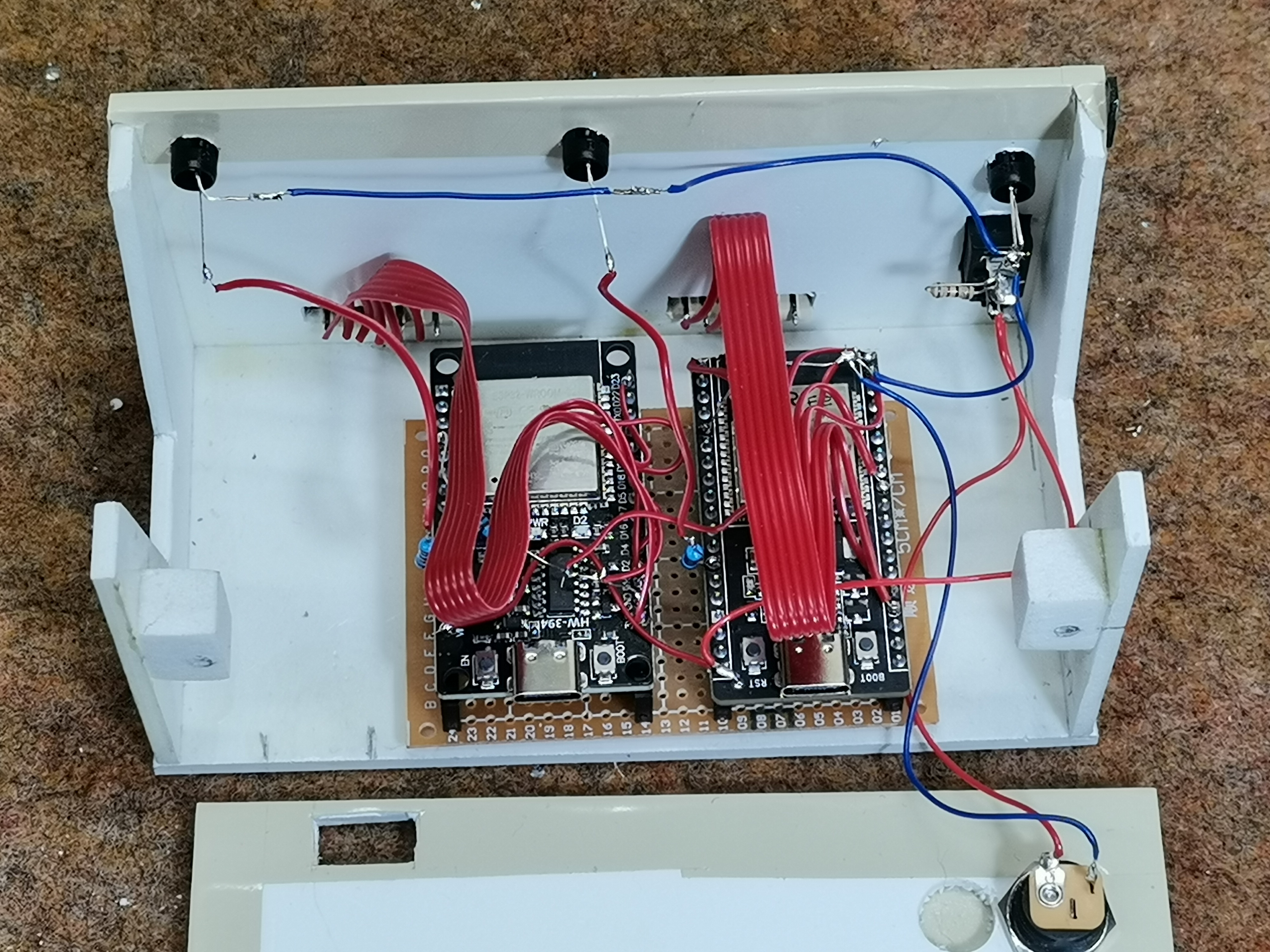
In particular, in this case I use the simplest passive envelope follower consisting of a diode and a capacitor, because the whole device is mainly intended as a demo device for testing, and based on this idea, a precise, fully functional audio VU meter can be made later with certain software and hardware modifications.
And now let's see how this VU meter works in real conditions.
Let me mention that a stereo potentiometer can be placed on the input in order to regulate the signal level, but for the sake of simplification I do it with the Windows mixer software.
And finally a short conclusion: This small, simple and interesting arduino project can be made in a few hours, and has a beautiful retro look, so you can use it as an additional part of any audio device, or as a stand-alone unit. With minimal code modification it can be used on many other devices (eg radio receiver) where signal strength measurement is required. The Vu meter is built in a suitable plastic box made of PVC material and lined with self-adhesive colored wallpaper.