


Story
Product Info: https://www.elecrow.com/wiki/esp-terminal-with-35inch-spi-capacitive-touch-display.html
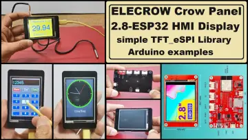
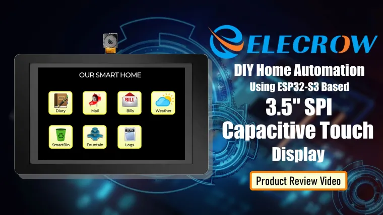
Elecrow sent me this cute little 320x480 ESP32-S3 based SPI capacitive touch display with OV2640 camera. I am going to use this screen to create a touch panel for my home automation system.
In this video, I am going to unbox and show you guys how to program and use this cute little touchscreen from Elecrow using SqareLine Studio.
You can order this touch screen display from www.elecrow.com. The product link is in the description below.
Table of Contents

I will start the video by unboxing the screen, followed by explaining its features and specification.
Then we will have a look at all the supported programming platforms.
Then I will show you guys the step by step instructions for setting up an Arduino IDE for programing this screen, followed by creating a simple user interface using the SquarLine Studio.
Next, I will show you guys my PHP, MySQL based SmartHome Web App. My aim is to create a User Interface similar to my SmartHome Web App using this display.
Finally, I will show you guys how I created the Arduino based "SmartHome App" for the touchscreen.
Unboxing

So, this is what arrived in the mail.
Inside the box is a USB-A to USB-C data cable and the main touchscreen display.
The screen is equipped with a powerful ESP32-S3 chip, and supports 2.4GHz Wi-Fi and Bluetooth 5 (LE), providing powerful computing and processing capabilities to your IoT applications.

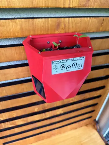
Combined with a microphone, 2M pixel camera interface and a buzzer, this screen is very user-friendly and can be used in various DIY projects, smart agricultural project, smart home and monitoring applications.
You can program it using Micropython, ESP-IDF and Arduino IDE. It also supports LVGL, which is the most popular free and open-source embedded graphics library to create beautiful UIs.
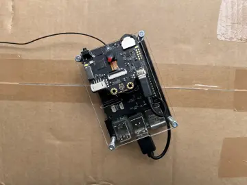
The PCB sits inside a cute looking black acrylic case. There are 2 x M3 screw holes for mounting the unit on a RAM Mount.

There are 4 Crowtail plug-and-play interfaces for interfacing the screen with various Crowtail sensors.
There is Lipo battery socket for standalone battery operated applications.
A Reset and a Boot Button.
An USB Type-C port for powering on and uploading sketches.
An I2C port, an UART for sending clockless serial data and a Micro SD Card Slot.
Alright, let's plug in the USB cable and let's see if the screen comes preloaded with any application. As you can see, the screen come preloaded with the LVGL graphics demo. The screen is very responsive and can display crystal clear images, texts, graphs, menu items and lots of other graphical objects.
The rest of the screen specifications are all listed on the screen.

Programming Environment Support

You can program the screen using VS Code, Arduino IDE, Espressif IDF, Esphome, LVGL, Micropython and PlatformIO.
In this tutorial, I am going to use the Squareline Studio to generated the user interface and Arduino IDE to program the ESP Microcontroller.
SquareLine Studio and LVGL

Squareline Studio is a next gen drag-and-drop UI editor for developing beautiful UI's for your embedded devices.
You can create custom components using the built-in widgets adding styles, animations and events for the screen.
Starting from images, bar graphs, line graphs, pie charts, menu items, checkboxes the screen can handle rich source of widgets.
SquareLine Studio is free for personal use. The latest version is 1.4.2 and is available for Windows, Linux, and MAC OS. You can download it from https://squareline.io/.

Configuring Arduino IDE

To get this screen to work with Arduino IDE and LVGL library, we need to make some config changes to our Arduino IDE.
Step1:
Lets first install the ESP32 Board Package. Please install v2.0.8 before installing the latest one. If you first install the latest one you will get a missing library error while compiling your code.
Step2:
Once installed lets configure the ESP32 Board.
Go to Board > ESP32 and then select "ESP32S3 Dev Module".
Then, select the correct COM Port under the Ports section. In my case it is COM9.
Scroll down and select the Flash Mode as "QIO 80MHz" and PSRAM as "OPI PSRAM".
Step3:
Now, lets install the LVGL Library.
For this demo, I am installing LVGL library version 8.3.6.
We also need to install the LovyanGFX graphics library.
Step4:
After installing the LVGL library we need to configure few of its parameters.
Go to your Arduino libraries folder and open the "lvgl" folder. Copy the "demos" and the "examples" folder into the "src" folder.
If you don't do this, you will get errors about missing demo and example codes during compilation.
Now, copy the "lv_conf_template.h" and paste it in the "Arduino\libraries" folder.
Rename the file to "lv_conf.h" and open it for editing.
Go to line number 15 and change the value from 0 to 1.
Then, go to line number 88 and change the value from 0 to 1.
Next, scroll down to line number 730 and change the value of line number 730/732 from 0 to 1.
If you are using custom fonts, then enable the fonts that you are using in your code in here.
Step5:
Now, you need download the demo code from my GitHub repository.
This is the framework that you can use to write your own code.
Please make sure you download the SPI version of the code. Once downloaded unpack the code at any location of your choice and then go to the "LVGL_SPI_" folder.
Open up the ino file and make sure you have the "ui.h" file included in the header section.
Double check line number 33 and make sure you see "SPI" in there.
Then scroll down and verify that a function call to "ui_init();" is present on line number 177.
Now change the baud rate to "115200 baud". That's it, our Arduino IDE is now all set to program the screen.
Creating A Simple UI Using SquareLine Studio

Alright, lets create a simple user Interface (UI) using the SquareLine Studio Application.
Fire up the app and click on the "Create" icon. Then, select "Elecrow" option and scroll down and click on the ESP32 Terminal with Arduino-IDE option.
Give your project a name and hit the "CREATE" button.
By default, you will see a 320x480 blank white screen in the editor.
Lets first change the background color of the screen to black. Click the "STYLE (MAIN)" option from the right panel and enable the "BgColor" under "Background". Then you can either pick a color from the color palate or you can manually enter the hex code in the text box.
To add a button, click on the "Button" icon on the left panel. This will add a blue color button at the center of the screen. Then, click on the "Label" icon to add a label to the button. Change the text of the label from the right panel by modifying the text under the "Text" option.
Drag the sides of the button to change its size.
Now, click on the "Screen" icon from the left panel to add a second screen to the stage. Change its background color to purple and add a button to the screen.
To add an png image to the screen, click on the "ADD FILE INTO ASSETS" button and then browse for the file. Try to add tiny files to your project to avoid out of memory errors during compilation. Insert the image and then drag and drop it to wherever you want it on the screen. You can also add some text to the image by adding a label to it.
Now, lets add some actions to the buttons. Select one of the button and then click the "ADD EVENT" button from the right panel.
In my case I want the screen to change from screen 1 to screen 2 and vice-versa. So My trigger will be "CLICKED" and "Action" will be "CHANGE SCREEN" to Screen 1 or Screen 2 respectively. I also want to add a transition of "MOVE RIGHT" and "MOVE LEFT" when the buttons are clicked.
Then, repeat the same steps with the second Button.
Once done, hit the Play button on top and then test the UI components by clicking the buttons. Yaiii, that works..
Now, lets create the UI package and load it to the screen.
To do so, we need to go to the folder where we saved our "LVGL_SPI_" ino file. Grab the location of the folder and paste it to the "FILE EXPORT" locations under the "Project Settings".
Next, click on the "Export" menu and select the "Export UI Files" from the list. once exported you will see a massive list of *.c and *.h files in the selected location.
Now, double click and open the "LVGL_SPI_" folder and launch the "LVGL_SPI_.ino" file using Arduino IDE.
Connect the USB cable to the screen. Then press and hold the "Boot" button and briefly press the "Reset" button and finally release the Boot button. You will see on the serial monitor that the ESP32 terminal has entered download mode. Then go ahead and compile and upload the code. Please keep in mind that the program includes the memory intensive LVGL library, so the upload process will take way longer than any other code. Just be patient and wait for it complete.
Once the upload is done, you need to restart the board either by pressing the "Reset" button or by unplugging and re-plugging the USB cable. Boom, there you go, yaii... everything works as expected...

Smart Home App

So, here is a glimpse of my smart home web application.
The application is hosted on a Raspberry Pi home-server.
The frontend of the app is created using PHP and the data is stored in a MySQL database.

Various sensors installed in my house send their data to the Raspberry Pi server. The data is then saved in the MySql database and is presented to the users using google charts.
Using a PC or mobile I can access this app from anywhere inside the house.
I have also set up port-forwarding on my router which allows me to access this app from anywhere in the world.

Now, I am going to use this screen to create a touch panel for my home automation system.
Designing The SmartHome UI

Using the Squareline Studio, I am creating the frontend for the touch screen.
The work is still under progress, however, I have migrated fair bit of the web application to the touch screen.
Lets do a quick test using the built in simulator to make sure everything works as expected. Bingo.. That looks pretty decent isn't it..
So, lets go ahead and load these screens to the touch screen. Same as before press and hold the "Boot" button and briefly press the "Reset" button and finally release the Boot button. You will see on the serial monitor that the ESP32 terminal has entered download mode. Then go ahead and compile and upload the code.

So, this is how my final setup looks like. With 2x Power supply mode to choose from, this screen can be used either by hooking it up to a USB port or can be used as a stand alone screen with a rechargeable battery pack.
The best thing is, if you have any issues using this screen, there is tech team to provide you with valuable technical support. Email: techsupport@elecrow.com
Uses
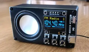
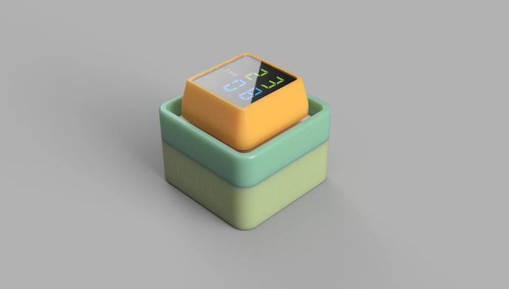
- Create a music player that stays near to your bed
- An alarm clock
- Musical photo frame
- Touch panel for home automation system
- And more..
Thanks
Thanks again for checking my post. I hope it helps you.
If you want to support me subscribe to my YouTube Channel: https://www.youtube.com/user/tarantula3
Video: https://www.youtube.com/watch?v=7ZQPPWMv1uQ
Full Blog Post: https://diy-projects4u.blogspot.com/2024/09/ElecrowSPIDisplay.html
Links
- Product Info: https://www.elecrow.com/wiki/esp-terminal-with-35inch-spi-capacitive-touch-display.html
- GitHub: https://github.com/tarantula3/CrowPanel-ESP32-Terminal-3.5-SPI
- Squareline Studio: https://squareline.io/pricing
- LVGL WiKi: https://docs.lvgl.io/master/intro/index.html
- SquareLine Studio Wiki: https://docs.squareline.io/docs/widgets/
- Elecrow How To: https://www.youtube.com/watch?v=ugoiicPM6U0
- Where To Buy: https://www.elecrow.com/esp-terminal-3-5-inch-320-480-spi-tft-capacitive-touch-display-with-ov2640-camera.html
- Tech Support Email: techsupport@elecrow.com
Support My Work
- BTC: 1Hrr83W2zu2hmDcmYqZMhgPQ71oLj5b7v5
- LTC: LPh69qxUqaHKYuFPJVJsNQjpBHWK7hZ9TZ
- DOGE: DEU2Wz3TK95119HMNZv2kpU7PkWbGNs9K3
- ETH: 0xD64fb51C74E0206cB6702aB922C765c68B97dCD4
- BAT: 0x9D9E77cA360b53cD89cc01dC37A5314C0113FFc3
- LBC: bZ8ANEJFsd2MNFfpoxBhtFNPboh7PmD7M2
- COS: bnb136ns6lfw4zs5hg4n85vdthaad7hq5m4gtkgf23 Memo: 572187879
- BNB: 0xD64fb51C74E0206cB6702aB922C765c68B97dCD4
- MATIC: 0xD64fb51C74E0206cB6702aB922C765c68B97dCD4
Thanks, ca again in my next tutorial.