Story
Electronic Timer
Circuit description
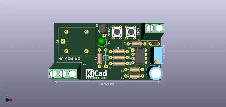
The proposed application will result in a general purpose programmable timer with output on a power relay. At the base of the circuit is the NE555 integrated circuit. The relay is operated when the START button is pressed and returns to the initial state after the delay time. The state of reset can be "forced" at any time by pressing the STOP button. The NE555 circuit is in configuration flip-flop-circuit; it can be seen as a flip-flop type flip-flop R-S; its inputs are pins 6 which represent the reset and 2 which is the set. The circuit also contains two comparators that lead the inputs from 6 and 2 and an output amplifier. Reset pin or "zeroing", is permanently connected to 12V (1 logic) and the operation of NE555 can be reset if pin 4 is connected to ground via the STOP button.
The delay time is: t = 1.1xRC where R = R3 + RV1, and C = C1. If R is in MOhm and C in uF, it follows that time is measured in seconds.
Example: R3 + RV1 = 1MOhm and C1 = 10uF: 1.1x1x10 = 11s
The delay time depends on RV1, it being the adjustment element of circuit, along with C1. As a result of pressing the STOP button on during a timing cycle, a new cycle can only be resumed pressing the START button again.
Some suggestions for choosing RV1 and C1: 2.5MOhm + 100uF = [110ms to 5min];
10MOhm + 47uF = [110ms to 9min]; 10MOhm + 100uF = [110ms to 19min].
It is noted the maintenance of the minimum value and a maximum possible value of 19s. Keep in mind the tolerances of components.
If the load is for AC, it is recommended that an RC series group be mounted on the relay contacts (R = 100Ohm / 1W and C = 220nF / 400Vac).
This circuit can be powered by 12V 200-500mA.
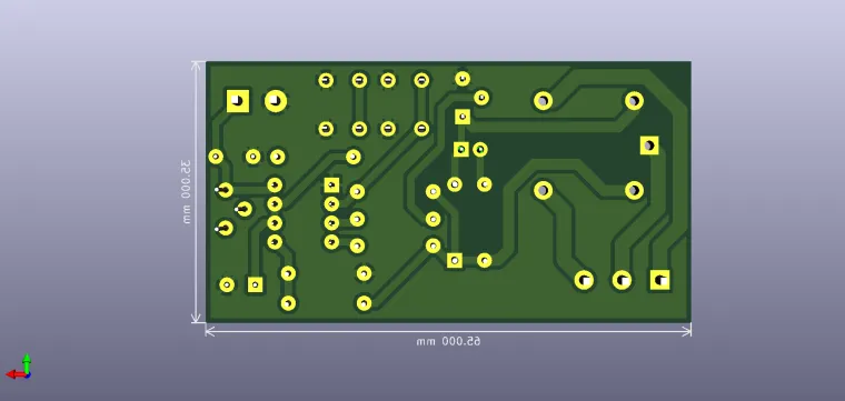
Note: The 3D model preview is just for aspect.


