Story
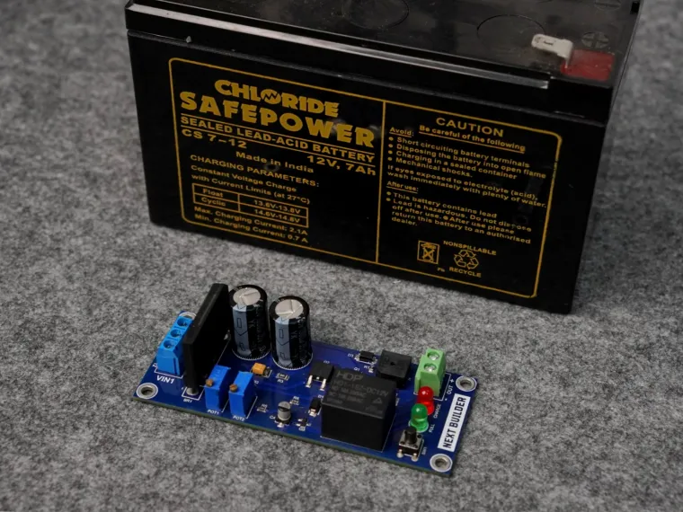
In today's world, batteries are an integral part of our lives, powering everything from our smartphones to electric vehicles. Having a reliable and efficient battery charger is essential to ensure optimal performance and longevity. In this project, we've developed a versatile smart battery charger that can be used to charge batteries ranging from 12V to 24V. This DIY project combines advanced electronics and user-friendly design to provide a convenient and effective charging solution.
The smart battery charger features:
- Wide Voltage Compatibility: Capable of charging batteries from 12V to 24V.
- Automatic Charging: Automatically adjusts charging parameters based on battery voltage and current.
- Overcharge Protection: Prevents battery damage by automatically stopping charging when the battery is fully charged.
- Buzzer Reminder: Also Remind, when the battery is full charged.
- Compact Design: Small and portable, making it easy to use in various settings.
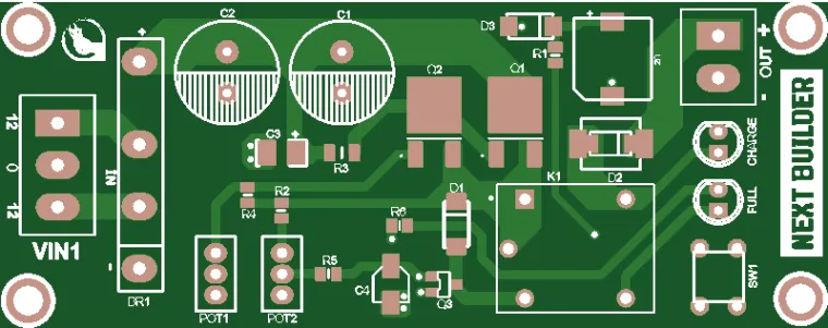
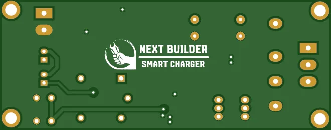
Let's start by design the PCB, first I designed the PCB in Kicad 8 Software. And after successfully design the PCB, I ordered it. And receive the pcb within a week.
Now it's time to Assembly the PCB. You can also choose pcbway assembly service or if you want to assemble it yourself then you have to order a stencil also for a better results. First match the stencil with solder pads & apply a small amount of solder paste. And now place all the components on there place according to BOM File. After placing all the components to it's place, now I use a Miniware MHP30 Hot Plate to melt the solder paste and solder the components.
Now after successfully Soldering the SMD components, it's time to solder the through hole component, you can check the BOM File for all comments details. Let's start by placing all comments one by one at there right place. After placing start with the soldering of the components using miniware TS80P Soldering Iron. Cut the extra part of the components & clean it properly using ISO propyal alcohol.
Now do the connection between transformer & the PCB;)
Let's understand the transformer wires first. In some transformer there're three wires (12-0-12). And in some transformer there're two wires only (12-0), if we coustmized it according to our needs.
- First, If we use (12-12) at once together then the output will be 24v and it will be used to charge the battery around this voltage.
- Second, if we use (12-0) wire at once together then the output will be 12v and it will be used to charge the battery around this voltage.
Now let's understand the PCB connection there're three wires connector also, marked as (12-0-12). Connect the wires according to your needs, for example if I have to charge the battery which have a voltage around 12v so I will connect the transformer 12-0 wire to 12-0 connector of PCB. I hope you understand the 24v battery charging Connection also.
Now let's understand how to do the calibration of the circuit. Calibration mins set the charging voltage & Auto Cut off voltage. The first Potentiometer is for set the charging voltage, by rotating this clock wise & anti clock wise you can increase and decrease the voltage. The second Potentiometer is for, set the Auto Cut off voltage, rotate it slowly to clock wise until the green LED turns on. Hope you understand it clearly.
Now our PCB is ready for charge any kind of battery. Connect the transformer with the AC power supply and connect the output wires with battery. When the battery will be charged fully, the green LED will be start glowing & the buzzer will be start to generating the sound also.
By following the steps outlined in this article and leveraging the PCB fabrication, you can create a reliable and efficient charger that meets your specific needs. Hope you enjoyed this article. Support me for more cool projects, Like this article & do follow


