


Story
An analog VU meter, or Volume Unit meter, is a device used in audio equipment to display the level of audio signal in decibels (dB). It is commonly found on audio mixing consoles, amplifiers, and other audio equipment. The primary purpose of a VU meter is to provide a visual representation of the audio signal's amplitude, helping users monitor and control the signal level to prevent distortion or ensure proper recording and playback. Despite the prevalence of digital meters, analog VU meters are still appreciated for their nostalgic and classic appearance, and many audio enthusiasts prefer their aesthetic and the way they visually represent audio signals.
Unfortunately even nowadays these instruments are relatively expensive and their price is higher than several hundred dollars. This time I will present you a way to make such an instrument yourself, which according to the characteristics does not lag behind commercial devices of this type.
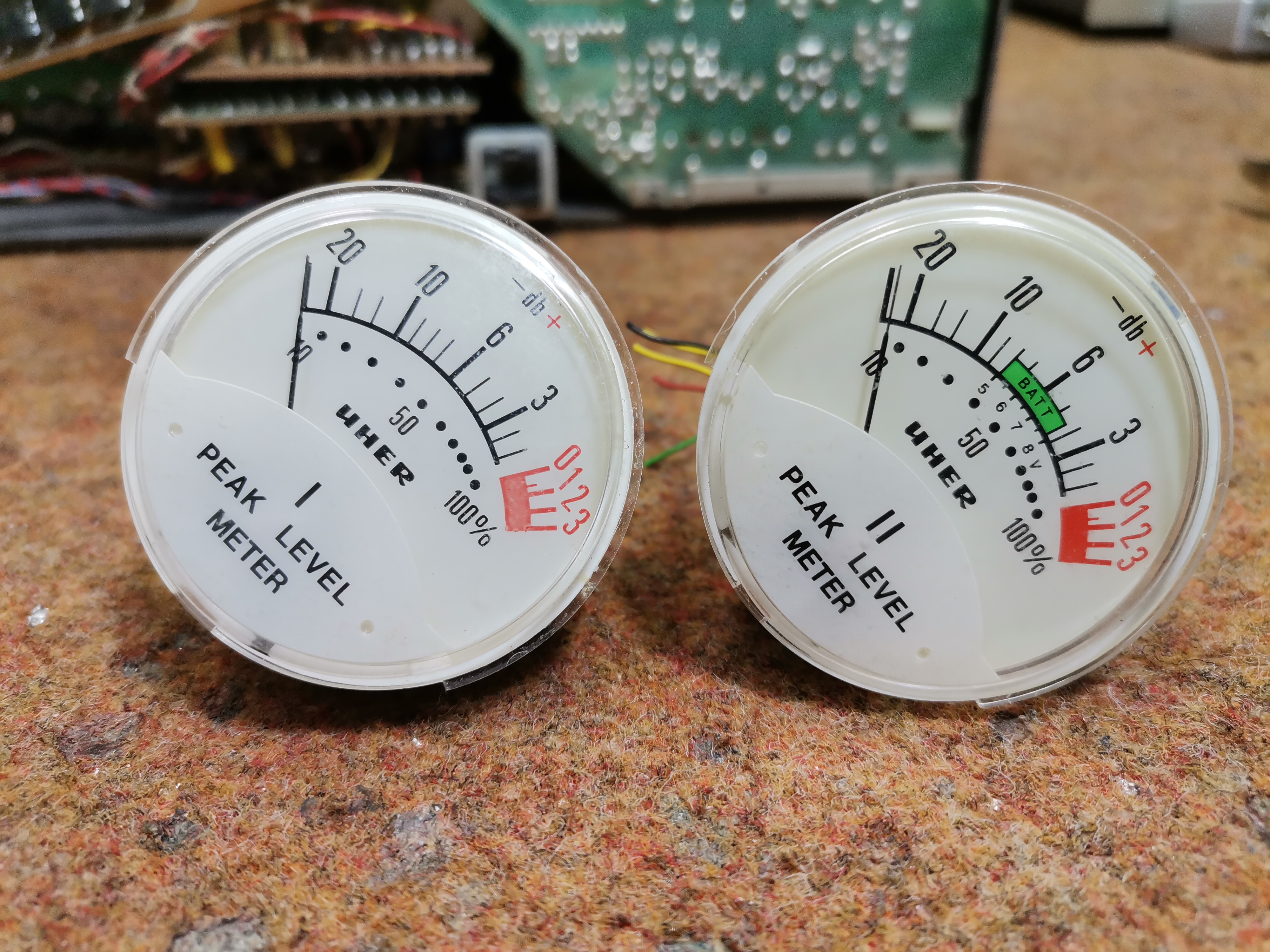
The most expensive part of these Vu meters are of course the galvanometers which are actually precision microammeters with a moving needle. Such instruments were commonly used in sound recording devices manufactured at the end of the last century and can easily be found in electronic waste disposal sites.
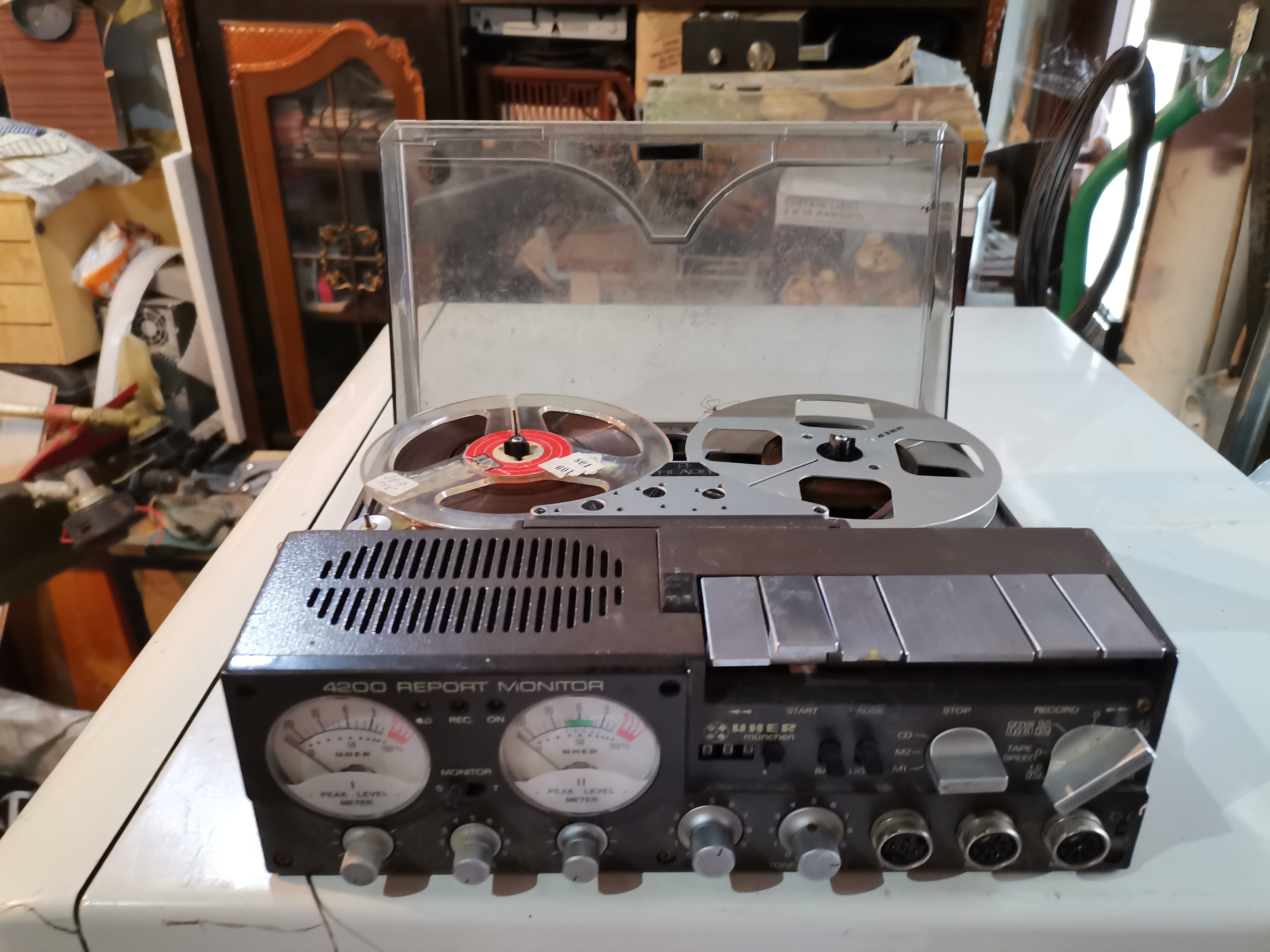
In particular I bought for $10 an old defective UHER 4200 Record Monitor tape recorder that contains two marked round VU meters with a built-in backlight. These instruments need to be connected to an audio signal source in some way.
For this purpose is used an electronic circuit (driver), which can be of passive or active type. The passive driver is simple to build but is relatively insensitive because you must overcome the voltage drop of the diodes with the signal. In that case, they are usually connected to the output of the amplifier and represent power meters.
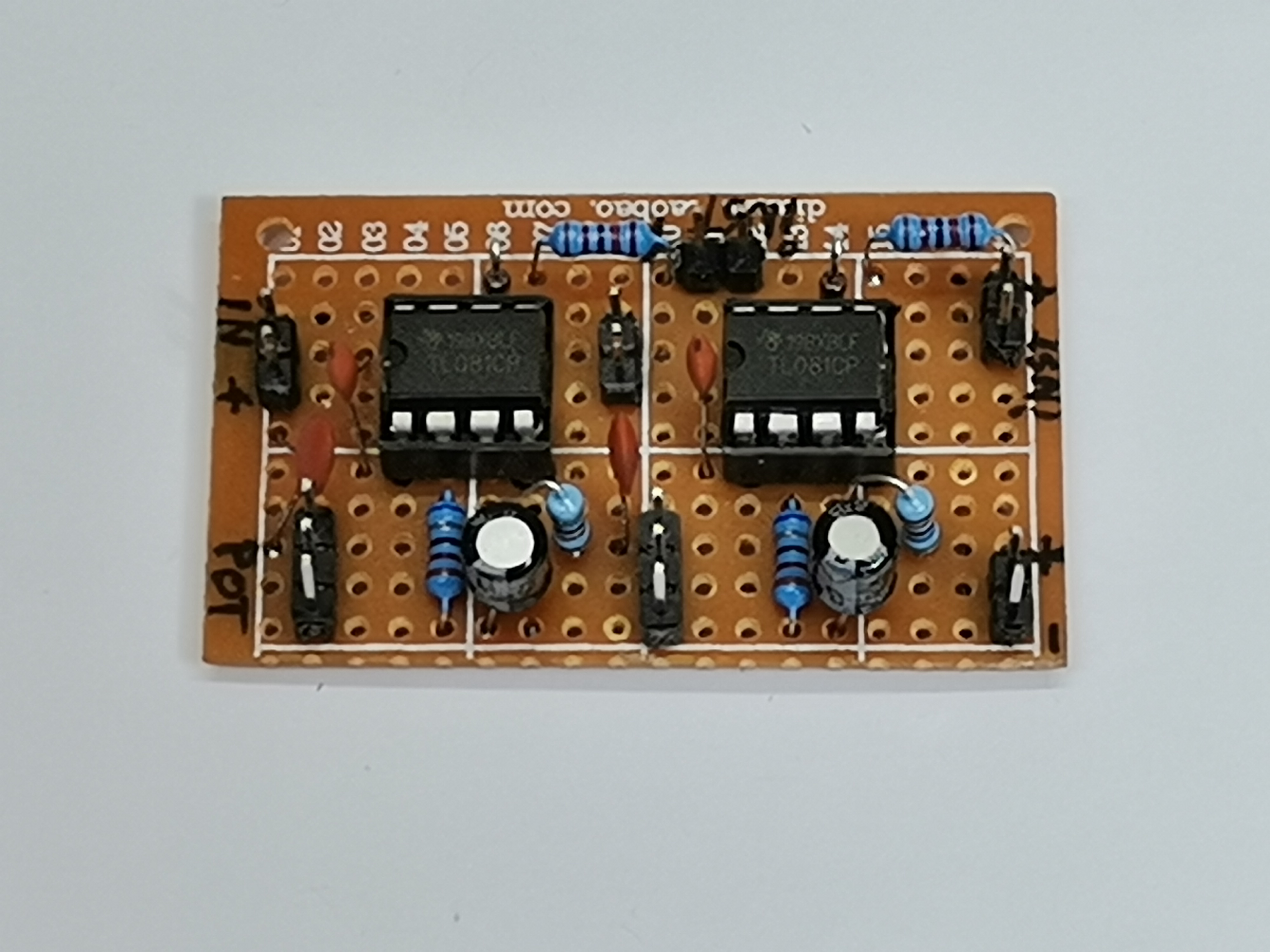
An active driver contains ICs or transistors as an amplifier, and despite the fact that it is very sensitive, has a high input resistance and does not affect the source signal at all. n this particular project I will use two identical active drivers for both channels.
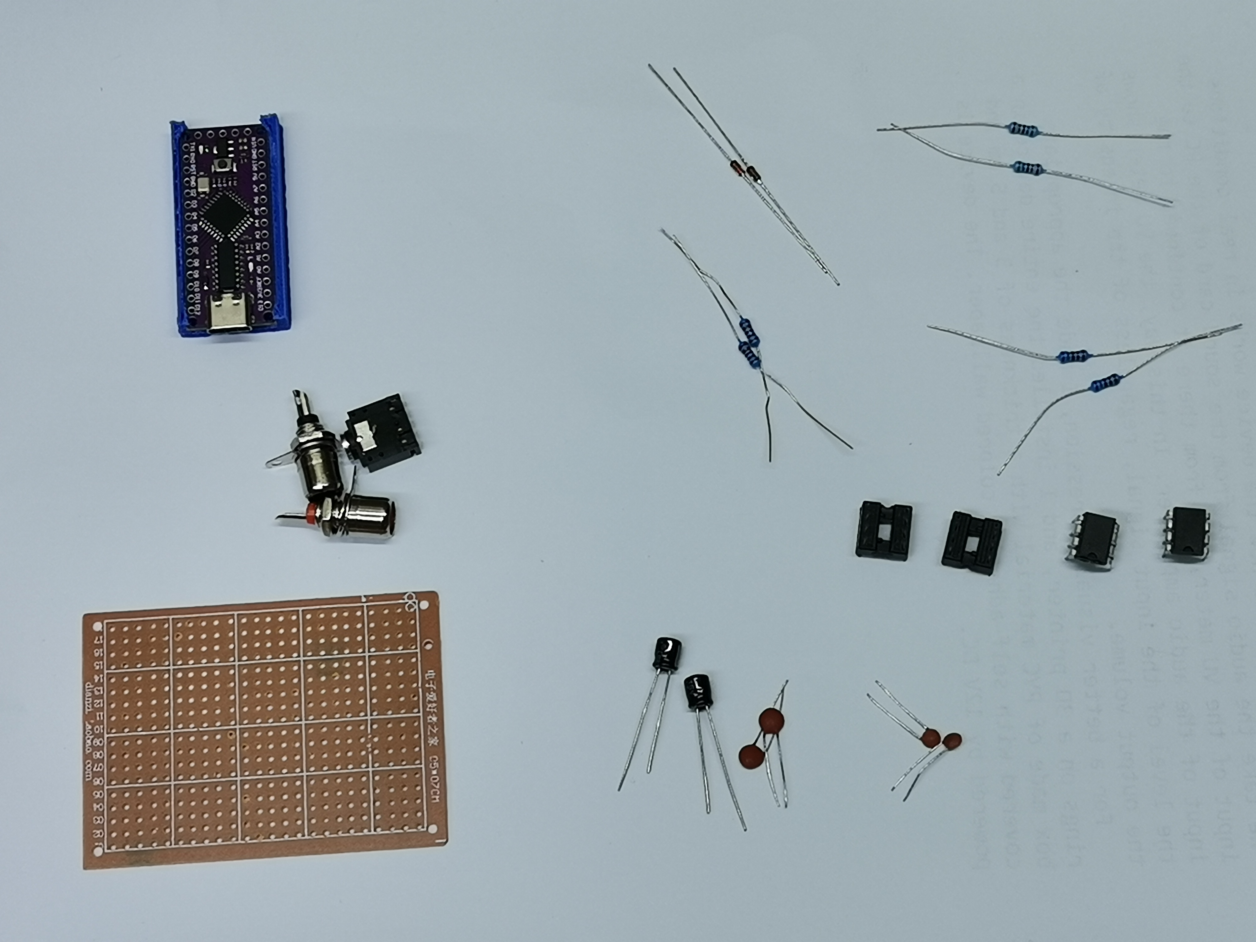
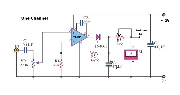
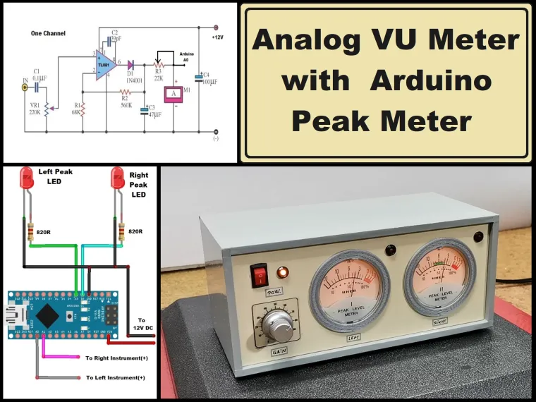
The device is relatively simple to build and consists of several parts:
- Two microamp meters,
- an operational amplifier IC (I used TL081, but another similar one can be used),
- some passive elements (capacitors, resistors and diode)
- and a potentiometer that changes the input sensitivity, and serves to calibrating the VU meter.

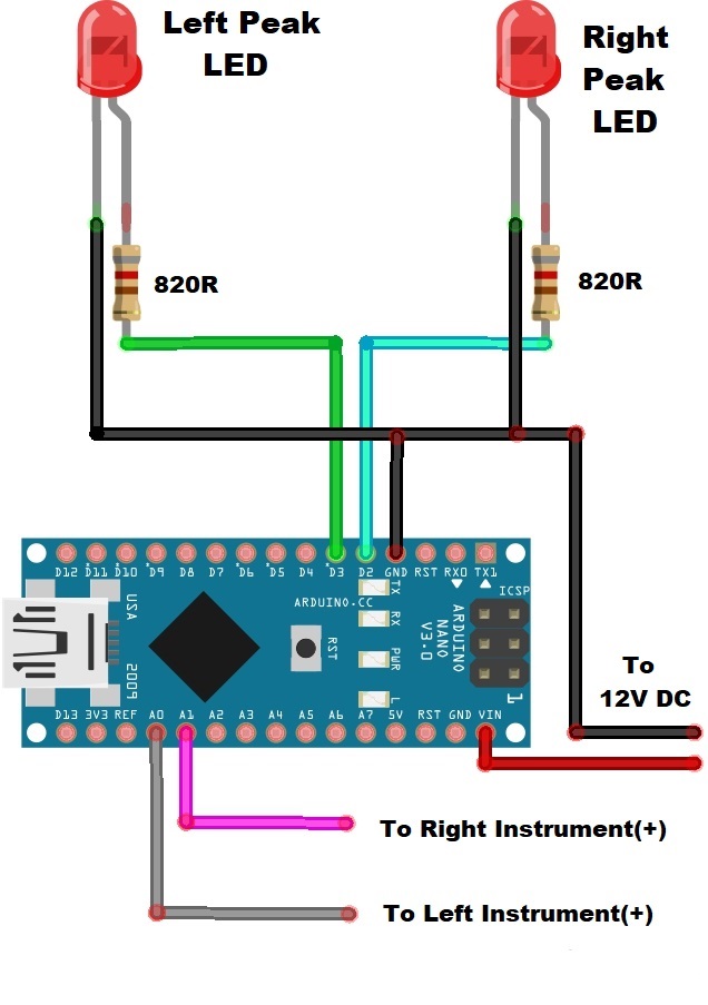
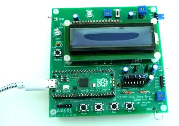
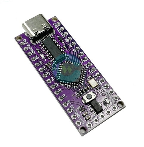
I also added a peak meter circuit, whose function is each time when the signal exceeds the specified level, turns on RED led. It was easiest for me to use an microcontroller for this purpose, because I can very simply and precisely set the activation threshold of the LED in the code. This is an Arduino Nano clone that costs less than $2 and doesn't add much to the cost of the device. Of course, if you have no experience with microcontrollers, you can make a very simple peak meter with transistors.
If we use the VU meter as an independent device as in my case, there is no need for calibration and the sensitivity can be adjusted with the potentiometer. Another option is to embed it in some audio device, for example between the preamplifier and the output amplifier, in which case we need to calibrate using a reference calibrated VU meter.
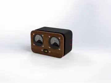
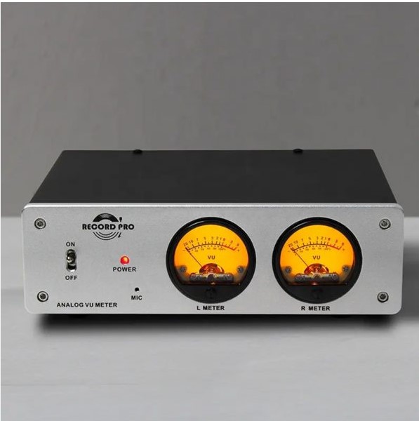
And now let's see how the device works in real conditions: We take the audio signal from the sound card of the PC to the input of the VU meter, and from there it continues to the input of the audio amplifier. In this way, the VU meter shows the level of the input signal, regardless of the intensity of the output volume. For a better visual impression, I made the appropriate rings on a 3D printer, and I installed the entire device in a box made of PVC material with a thickness of 3 and 5 mm and covered with self-adhesive colored wallpaper.
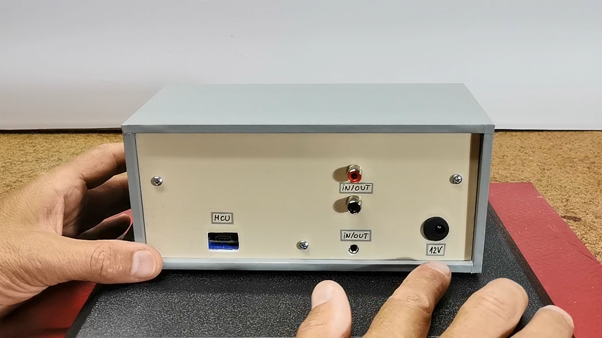
The device is powered by 12V DC.