


Story
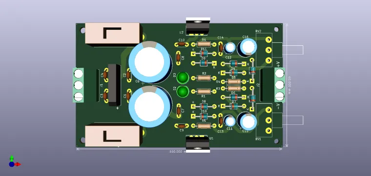
Differential voltage source
Circuit working principle
The application schemes of the already integrated classics LM317 and LM337 are used, but with the modified reference to increase the voltage from 0V. The power supply is made from a 24VA transformer that can provide 2x18V at 1.5A. The voltage is adjusted from the two potentiometers when used as a service source. Therefore, the LM317 and LM337 are part of the series of voltage regulators adjustable in the range of 1.25 V to 37 V at a current of 1.5A. The LM317 is designed as a positive voltage regulator and the LM337 is designed as a negative voltage regulator. These include a current limiting circuit, thermal overload protection and protection for safe operation.
The classic application of the LM317 controller is the one in the figure below:

The voltage at the output of the regulator is calculated by the formula:

The C5 capacitor is used for the rejection of transient signals from the output, the oscillations that would occur are integrated by this capacity. If it is used, the D9 diode is inserted, which turns the tips on the output line. Overload protection is very effective even when the V control terminal is detached. We therefore have extreme security. We have only one impediment to the classic scheme: the output voltage is not regulated from 0V precisely due to the voltage that falls on the two sets of the internal regulating transistors. The solution would be to lower the reference voltage by 1.25V, ie to compensate for the voltage that appears on the two junctions. This solution is applied in the figure below.

In this case, the voltage at the output of the regulator is calculated with the formula:

Given that the LM337 is identical to the LM317 as an internal structure, but designed for negative voltage, both the schematics and the calculation relations are valid:

80dB rejection is provided by C11 and C12. The source is protected with a 32mA fuse and the presence of the output voltage is indicated by LEDs D2 and D3 on the two sections. Diodes D8 and D9 have the role of protecting the regulators at reverse voltage applied to the output, in case we supply reactive loads.
Enjoy it!