


Story
Introduction
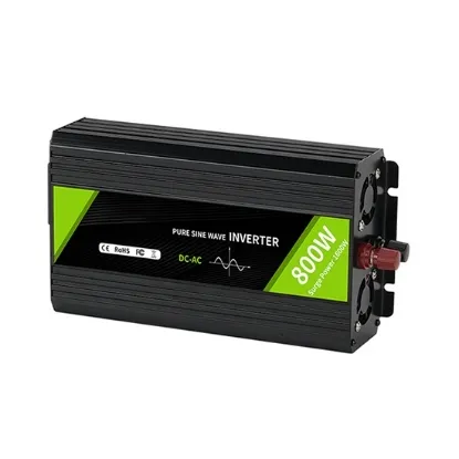
A pure sine wave inverter is a critical device. The highly efficient 12V/24V/48V pure sine wave inverter converts the DC power stored in the battery into standard household AC power, providing you with quiet AC power anytime and anywhere. Sine wave inverters are commonly used in a variety of applications, including off-grid or backup power systems, RVs, marine, and renewable energy installations. They provide reliable and high-quality power, ensuring that electrical equipment operates efficiently and minimizing the risk of damage or failure. This type of inverter is highly sought after due to its ability to provide clean power with very low harmonic distortion, making it ideal for powering sensitive electronics, medical devices, and household appliances. This project will delve into the design and implementation of a pure sine wave inverter, covering the key components, design principles, and practical considerations involved in creating a reliable and efficient inverter system.
Design Principles
Building Blocks
A typical pure sine wave inverter consists of several key components:
1. DC Input Stage: This stage involves converting the battery voltage (usually 12V or 24V) into a higher voltage DC source. This is often achieved using a DC-DC converter.
2. Inverter Stage: The core of the inverter, where the high voltage DC is converted into an AC waveform using pulse width modulation (PWM) and an H-bridge configuration of power MOSFETs.
3. Transformer: A transformer is used to step up the voltage to the desired AC level (e.g., 120V or 220V) and to provide electrical isolation between the DC source and the AC load.
4. Control Circuitry: This includes a microcontroller or digital signal processor (DSP) that generates the PWM signals, monitors the output voltage and current, and provides protection features.
Inverter Mode Operation
In the inverter mode, the low voltage DC power is first converted to a high voltage DC source, and then to an AC waveform using PWM. The H-bridge circuit converts the battery DC voltage into AC using high-frequency PWM (6 kHz to 20 kHz), feeding a 50-Hz transformer which boosts it to 120V/220V AC. The output voltage is sensed through an auxiliary secondary winding and fed back to the controller, which adjusts the PWM to generate a regulated AC output.
Mains Mode Operation
In the mains mode, when the input AC is present and within a valid range, the relay between the input AC and the inverter output is closed, allowing the input AC to directly power the load. The same AC is also used to charge the battery through the H-bridge, using a bridgeless rectification principle.
Switching Waveform Details
Inverter Mode
The switching waveform in the inverter mode is generated by modulating a sine wave with a high-frequency square wave. The positive peak of the sine wave is represented by the maximum duty cycle, and the negative peak by the minimum duty cycle. This results in a trilevel PWM signal that is used to drive the H-bridge MOSFETs.
Mains Mode
In the mains mode, both high-side MOSFETs are switched off, and both low-side MOSFETs are switched with a PWM waveform. The duty cycle of the lower-side PWM signals determines the charging current. The charging current is proportional to the duty cycle of the PWM switching on the lower-side FETs.
Schematic of the Design
The schematic of a pure sine wave inverter is typically divided into two main sections:
1. Main Power Board: This includes the DC-DC converter, H-bridge circuit, transformer, and output filtering components.
2. Microcontroller Daughter Card: This houses the microcontroller, gate driver, current sensing circuitry, and protection features.
Key Components
1. DC-DC Converter: A buck converter like the TPS54231 is used to convert the battery voltage to a lower voltage required for the control circuitry.
2. Gate Driver: A highly integrated gate driver like the SM72295 is used to drive the power MOSFETs in the H-bridge. It provides high current drive capability and includes features like overvoltage protection and current sensing.
3. Protection Circuits: Overcurrent discharge (OCD) and overcurrent charge (OCC) protection are implemented using comparators like the LM339. These circuits monitor the current through the battery and shut down the PWM if the current exceeds safe limits.
Implementation
Hardware Setup
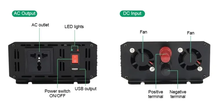
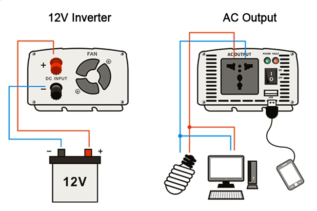
1. Battery Connection: Connect the battery to the DC input terminals of the inverter. Ensure that the connections are secure and that the battery is adequately rated for the inverter's power requirements.
2. Transformer and H-Bridge: Assemble the H-bridge circuit with the power MOSFETs and connect it to the transformer. Ensure that the transformer is rated for the desired output voltage and current.
3. Control Circuitry: Program the microcontroller to generate the PWM signals and monitor the output voltage and current. Implement the feedback loop to regulate the output voltage.
Testing and Debugging
Initial Testing: Start with a no-load test to ensure that the 12v pure sine wave inverter produces a clean sine wave output. Check the output voltage and frequency using an oscilloscope.
Load Testing: Gradually increase the load on the inverter and monitor the output voltage and current. Ensure that the inverter maintains a stable output under different load conditions.
Protection Features: Test the overcurrent and overvoltage protection features by simulating fault conditions. Ensure that the inverter shuts down safely and does not damage the components.
Conclusion
Designing and implementing a pure sine wave inverter involves careful consideration of the various components and their interactions. By following the design principles outlined in this article, you can create a reliable and efficient inverter system that provides clean power for a wide range of applications. Always ensure that safety precautions are taken during the design and testing phases to avoid any potential hazards.