


Story
Car Battery Monitor
Circuit presentation
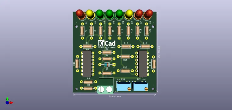
The electronic circuit presented indicates the value of the voltage with eight LEDs, namely the following voltage levels: 10; 10.5; 11; 12; 13; 14; 14.5 and 15V. Because the values ??of 10; 10.5 and 15V are considered 'dangerous', they are signaled with red LEDs. For the values ??of 11 and 14.5V, considered as 'warning' values, yellow LEDs are used, and for the voltages of 12, 13 and 14V, considered as 'normal' values ??for a car battery, they are marked by green LEDs.
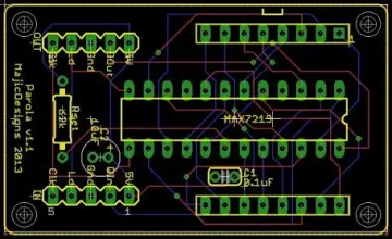
Description of the wiring diagram
The car battery connects to the J1 connector terminals. Accidental polarity reversal leads to degradation of integrated circuits U1 and U2. With the help of the 5.6V Zener diode and the R1 resistor, a stabilized fixed voltage is obtained which will ensure the correct (accurate) measurement of the battery voltage. Resistors R4 ... R19 (series) set the toggle thresholds of the 8 operational amplifiers and are connected to the reversing gates. With the help of the RV2 semi-adjustable, the tilting threshold is established for the minimum indication value of 10V. The non-inverting inputs are connected together and are polarized by the resistive divider R1-RV1. With the help of the semi-adjustable RV1, the correct indication of the maximum voltage value of 15V is established. The voltage applied to the non-reversing gates is not stabilized and will depend on the value of the battery voltage. When the voltage value is 10V, LED D9 (red) lights up and when it reaches 15V all LEDs will light up, including the last LED - D1 (red). In the voltage range with values ??between 10 and 15V, the other LEDs will light up, in the value levels mentioned above. For example, for the 12.6V value of the battery, LEDs D6, D7, D8 and D9 will light up, which means that the voltage value is higher than 12V, but lower than 13V.
Realization and commissioning
The installation is supplied from an adjustable and stabilized source with a voltage of 15V. Pay attention to polarity! The voltage value must be controlled with a precision voltmeter, preferably electronic. The correct calibration of the device will depend on the accuracy of this measurement. Carefully adjust the RV1 semi-dimmer until the LED lights up (red) - D1. In this situation, all other LEDs must be lit - D2 ... D8. The setting will be correct when the supply voltage is reduced to 14.9V, LED D1 will turn off and at 15V, it will light up. Lower the supply voltage to 10V. Adjust the RV2 semi-dimmer until the LED (red) - D8 lights up. Similar to the 15V voltage setting, lowering the voltage value to 9.9V, the D8 LED should turn off and on at 10V. The correct indication of the device will depend on the accuracy of these settings. The display accuracy also depends on the tolerance of resistors R4 ... R19. If 5% tolerance resistors are used, the indicated voltage values ??will not differ by more than 0.1V.
Bill of materials:
|
"Component Count:" |
"34" |
|
"Ref" |
"Value" |
|
"D1" |
"LED_R" |
|
"D2" |
"LED_Y" |
|
"D3" |
"LED_G" |
|
"D4" |
"LED_G" |
|
"D5" |
"5V6" |
|
"D6" |
"LED_G" |
|
"D7" |
"LED_Y" |
|
"D8" |
"LED_R" |
|
"D9" |
"LED_R" |
|
"J1" |
"Battery" |
|
"R1" |
"10k" |
|
"R2" |
"1k" |
|
"R3" |
"680R" |
|
"R4" |
"330R" |
|
"R5" |
"680R" |
|
"R6" |
"330R" |
|
"R7" |
"680R" |
|
"R8" |
"330R" |
|
"R9" |
"680R" |
|
"R10" |
"330R" |
|
"R11" |
"330R" |
|
"R12" |
"330R" |
|
"R13" |
"680R" |
|
"R14" |
"330R" |
|
"R15" |
"330R" |
|
"R16" |
"680R" |
|
"R17" |
"330R" |
|
"R18" |
"680R" |
|
"R19" |
"330R" |
|
"R20" |
"680R" |
|
"RV1" |
"10k" |
|
"RV2" |
"10k" |
|
"U1" |
"LM324" |
|
"U2" |
"LM324" |
Enjoy it!