Story
What is it?
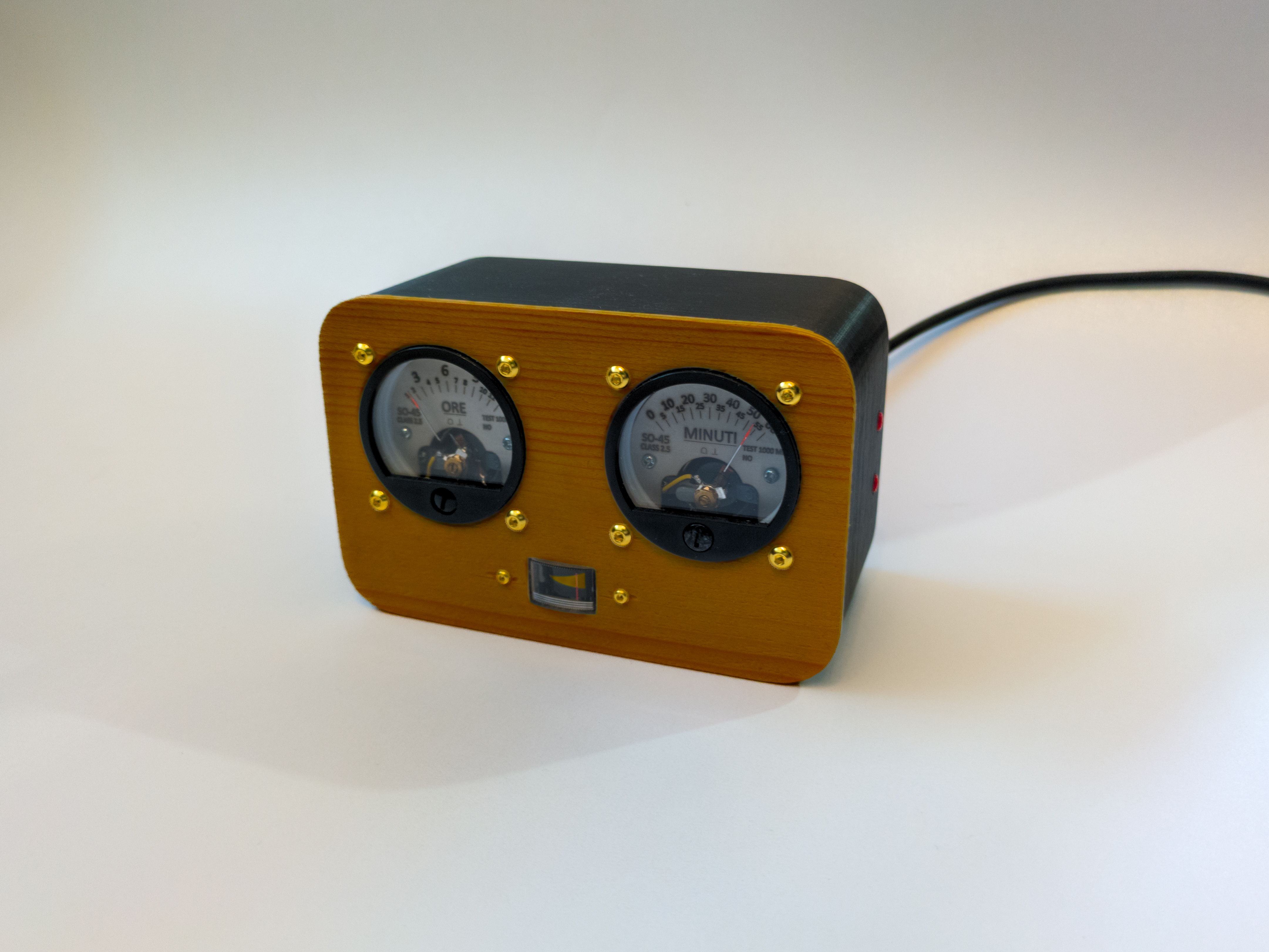
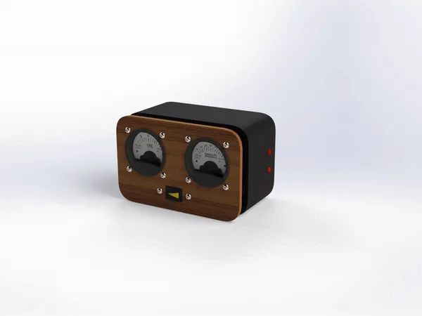
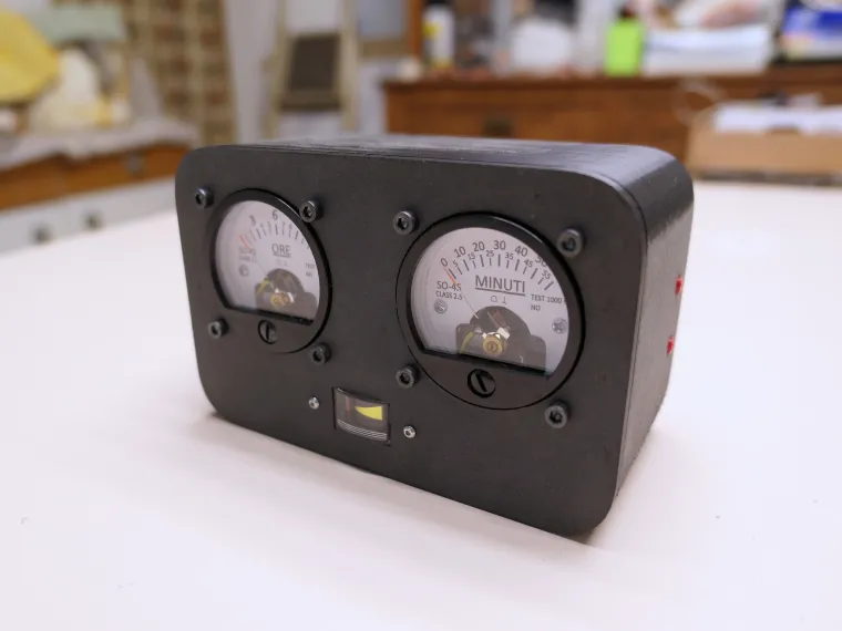
The Floppy Voltmeter Clock is a special clock that instead of using the usual rotating hands, or seven-segment displays in the case of digital clocks, uses two analogue voltmeters in a retro style. It is therefore a unique and very special object. It is designed to be open source and easily made, so anyone can create one and put it in their desk, workshop or living room.
The idea
Wandering around on YouTube I have seen that lately many people are building systems to display the time, some are mechanical, others electromechanical and still others completely digital. So I got the idea to make a special clock of my own, and here is the Floppy Voltmeter Clock made with analog voltmeter✨
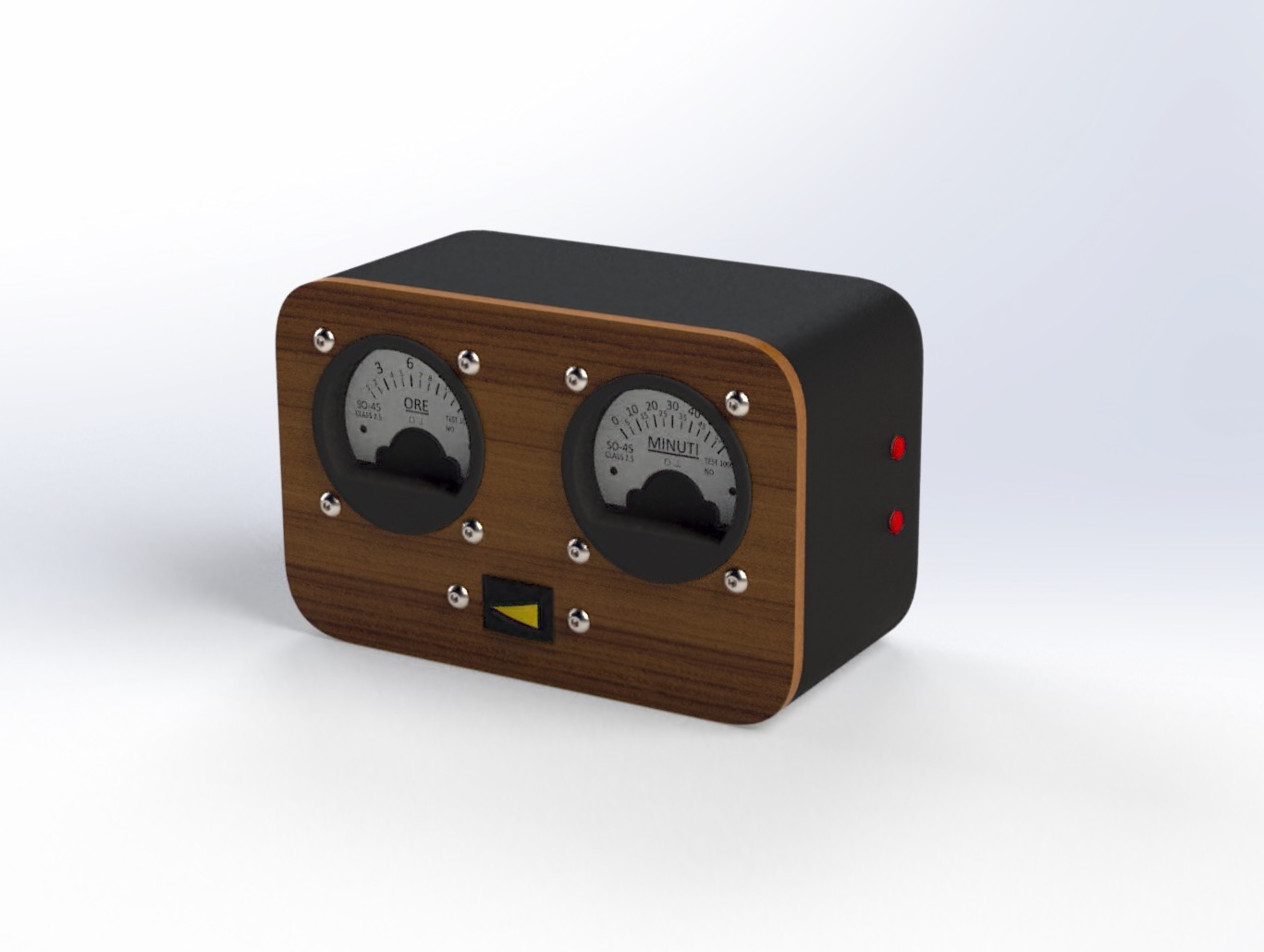
So I made a control board and case designed to be fully 3D printed so anyone can replicate it, but the original idea is to use a CNC and mill the faceplate in wood, to give it that extra touch of quality.
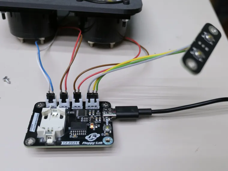
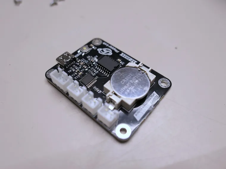
Control board
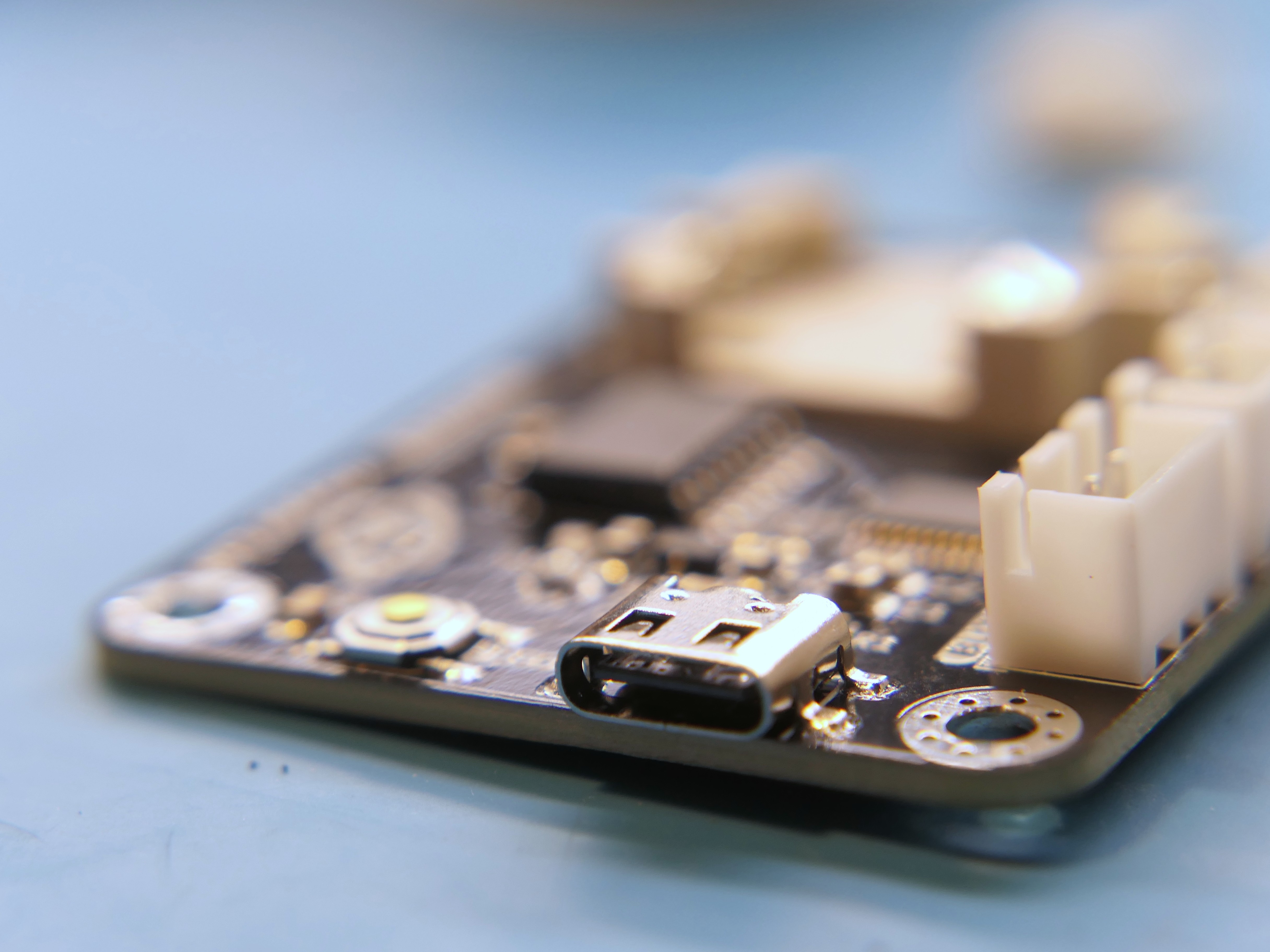
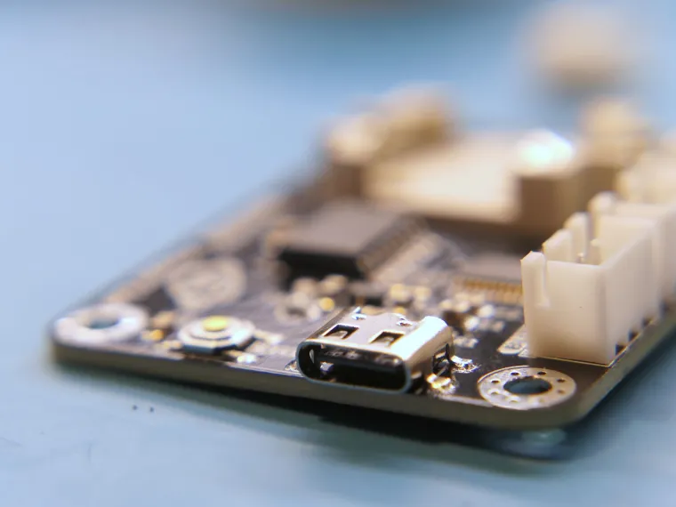
Like most of my projects, this one is also based on an STM32 microcontroller, which retains the cheap design but still has good computing power and all the necessary peripherals for the project. Actually, this microcontroller is also far too well equipped. To be precise, it is an STM32G030F6P6 with 32KB of Flash memory and a lot of internal modules, such as two I2c, two SPI, two UART, a 12bit ADC and no less than 8 timers... So yes, it's all too much 🤯
Two are mainly needed in this project:
- A timer for generating PWM signals;
- The I2C communication module for communicating with the external RTC.
Everything is conveniently powered by a phone charger with a USB-C cable. It consumes very little power, we are talking a few milliamperes.
I did some tests and the average consumption is only 16 mA, that's very little! So any phone power supply is fine, in fact it won't even feel your clock connected.
External RTC
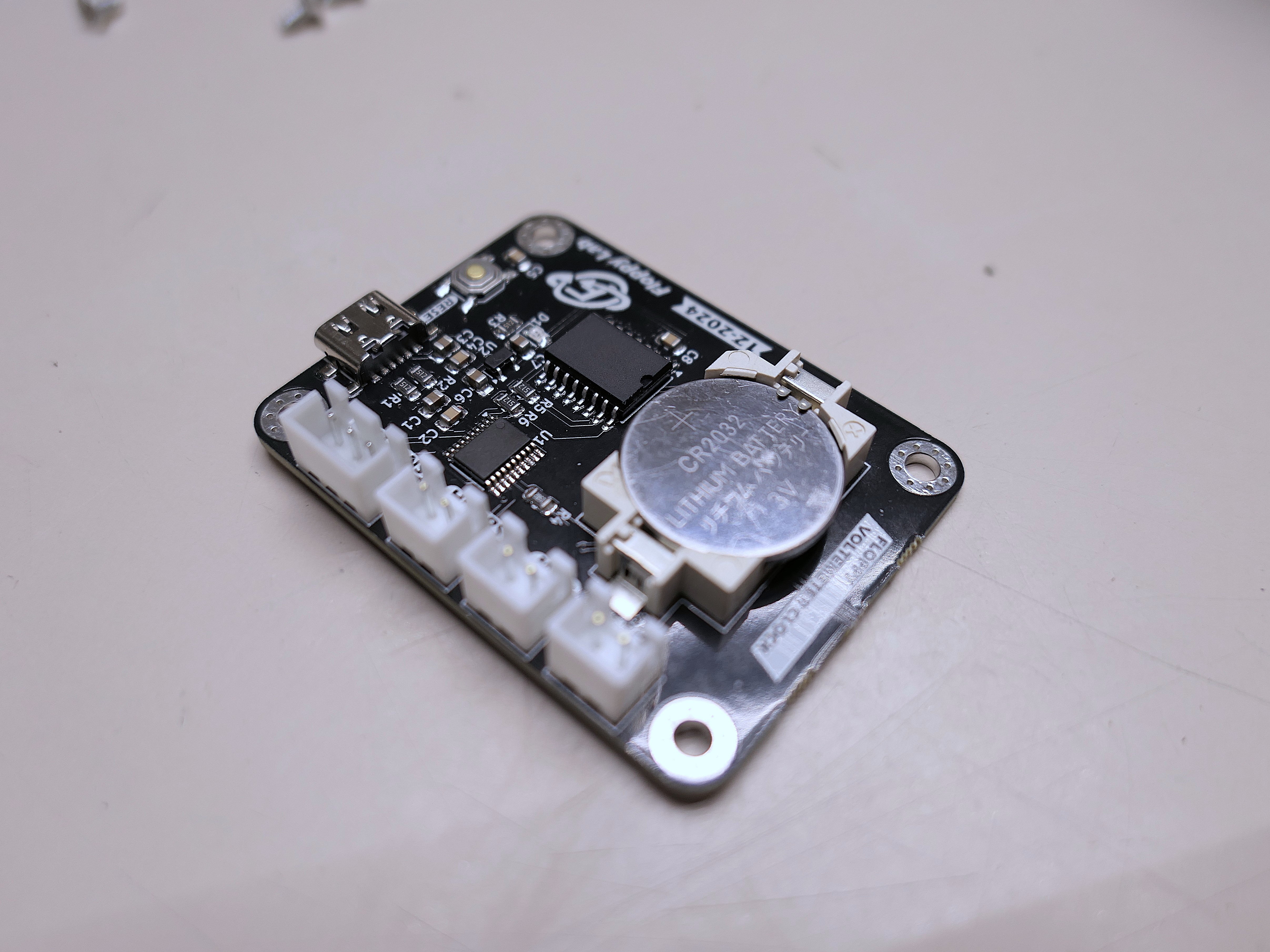
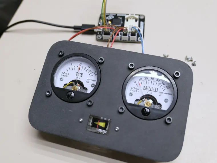
Obviously being a clock it needs to keep time 🤣, to do this I could have used the internal RTC module by adding an external oscillator. But I decided to use an external IC, so I have a very accurate and temperature compensated RTC with integrated oscillator. I used a classic DS3231, which is very easy to use as only I2C serial communication is required. So I connected the SDA and SCL of the microcontroller to the respective pins of the integrated RTC and that was it.
Then the firmware handles all the reading of the exact time and setting the time in case you want to change it.
Since the clock is powered via USB-C, if the power fails the whole thing would forget the time set and you would have to reset it each time. To solve this problem, the integrated DS3231 allows a 3V battery to be added as an auxiliary power supply in the absence of the main one. So, as you may have noticed, there is a CR2032 button battery that maintains the time when there is no power from your phone charger.
PWM & Voltmeter
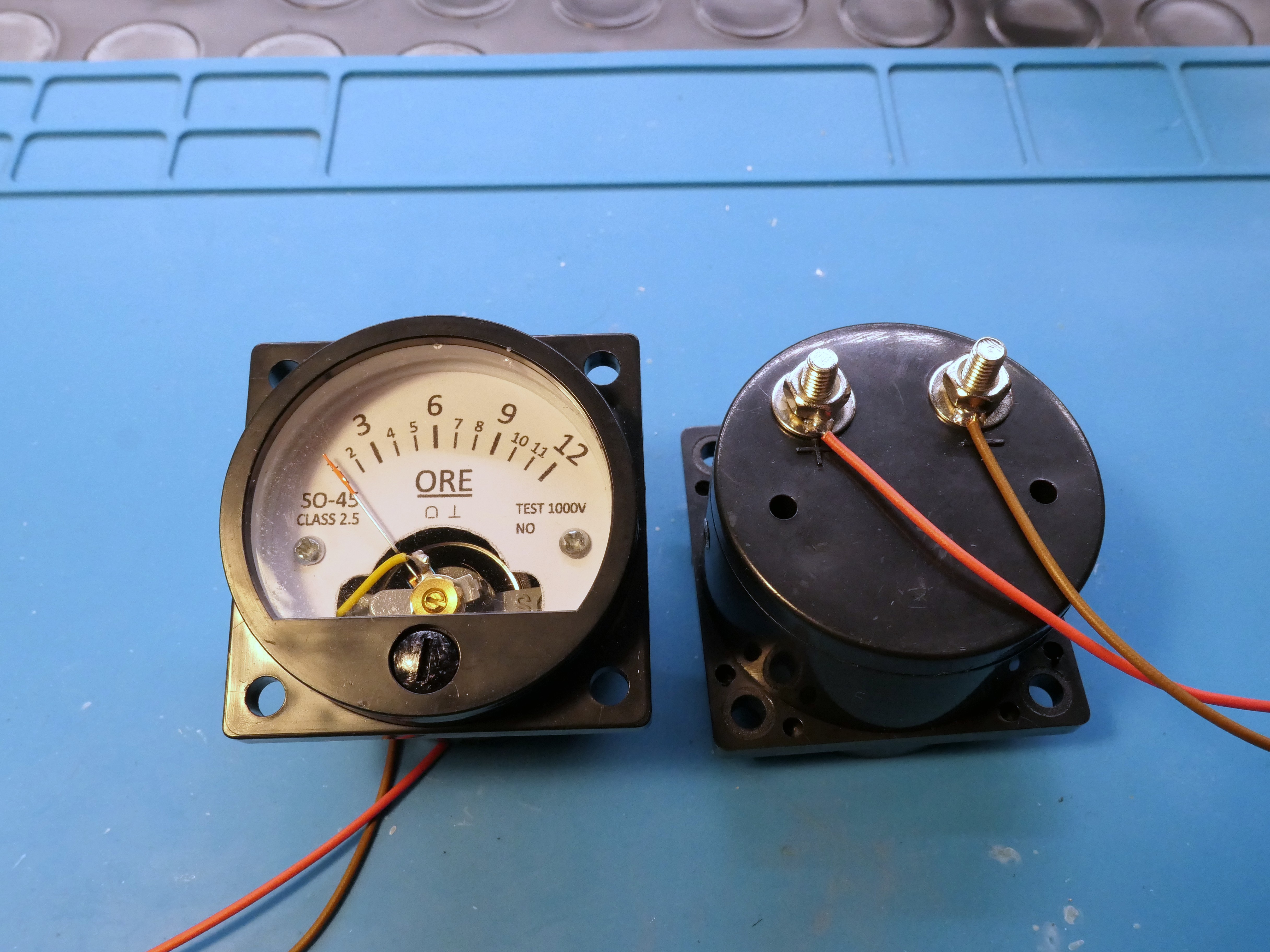
As anticipated, the idea was to use voltmeters instead of the hands of a classic clock. So I bought two with a rating of 3V and a smaller one that is actually a microammeter with a range from 0 to 200uA.
The two voltmeters display hours and minutes, while the small microammeter displays seconds.
For the hours and minutes I modified the internal panel, inserting a modified graphic so as to see the hours and minutes written and understand what you are looking at. The new graphic was printed on a simple sheet of paper and then glued over the original one. This is the only modification necessary for the creation of this clock, so once done it's all downhill!
The hands of the voltmeters (and also the ammeter of the seconds) are moved by a PWM signal generated by the microcontroller. Since the MCU is powered by 3.3V the output is practically perfect for the range taken. So with a small function in the code you generate a PWM signal with the duty cycle with the correct percentage for the position of the hand. The voltmeter then automatically averages the value and displays a fixed voltage.
To make the correct current flow for the seconds I simply added a 15KOhm resistor in series with the ammeter so as to convert the 3.3V into 220uA so as to control the latter perfectly as well.
Case
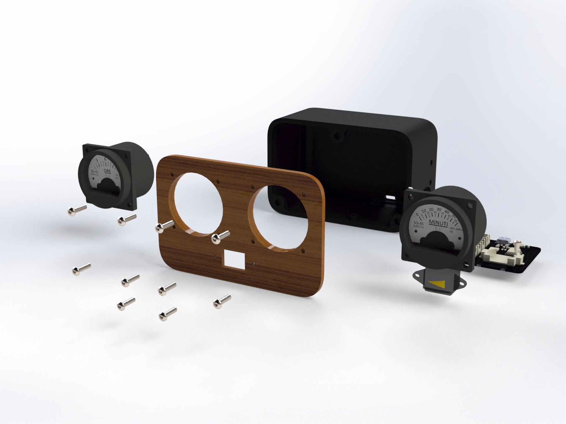
The case was designed to have a minimal style. The whole thing can be completely 3D printed. To give it a more elegant touch I thought that the front part could be milled in wood with a CNC, I will try soon and once done I will publish the video of the project on my YouTube channel, so you too can find all the details and demonstrations.
On the back of the case there is the USB-C port for power, instead on the right side there are two buttons, one to set the hour and the other for the minutes. This allows you to reset the time easily by pressing one or the other button.
If you have instead wondered how to change the button battery since it is closed inside the case.. Well the answer is: there are no screws that close the front part from the back, but I created a magnetic closing system, so you just have to glue the magnets and everything remains closed. And so you can simply remove the front panel and open the case, remove the old battery and insert the new one.
Probably once you put the new battery there will be no need to change it for a few years🤣
BOM list
(I have to find a different supplier or change the ammeter for the seconds, because I can't find any around. All the more reason to make a kit with everything you need)
Conclusions
I had a lot of fun making this project and I'm sure you'll have fun building one too!
You can find all the files needed for both production and the 3D printed case here or in the GitHub repository, so if you want to make changes you can download and modify everything you want.
I hope you enjoyed this project and that it inspired or encouraged you to create one too. For more information I suggest you subscribe to my YouTube channel so you don't miss updates on the project, there is a possibility that I make kits, so you have everything available without having to order things separately and/or program the board yourself. (I will update this post if I see interest on this).
Be sure to leave a comment with suggestions or if you liked this project. Thank you and see you next time!


