


Story
Battery Cell Charger
Circuit Operation
?
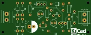
The assembly ensures the charging phase with limited current and constant voltage. The low voltage charging current of the transformer passes through the transistor Q1, the diode D7, the battery and the resistor R3 back to the mains supply. The passing current creates a voltage drop in R3, which opens Q2. Transistor TQ controls the current flowing through Q1 - the current is adjusted so that there is approximately a constant voltage drop in R3. LED D5 is connected to collector Q2, which indicates the current charging phase. The resistance of the resistor R1 is intentionally chosen to be relatively low, so that a substantially higher current flows through the resistor than is necessary for the control Q1. Most of this current then flows through LEDs D5 and Q2. Therefore, the LED illuminates at an approximately constant brightness throughout the current charging phase. The D5 LED connection limits the minimum output voltage at which the circuit is operating properly to about 1 V. Since even a discharged battery still has a voltage higher than 3 V, this is not a fault. Part of the output voltage stabilization circuit does not apply during the current charging phase. LED D6 is low and low current. The TL431C stabilizer is only applied when the final voltage is reached. As the voltage increases, the current IO begins to flow, while the current flowing Q2 decreases. The final charging voltage is set by the divider R5, R6 and R7. Resistor R7 is used for precise setting of the output voltage. The function of the TL431C circuit is very simple - if the voltage at input R increases by more than 2.5 V, the current flowing between terminals K and A. The capacitor C2 increases and the resistance R7 ensures the stability of the regulator.
In the constant voltage charging phase, LED D5 goes out (Q2 closes) and LED D6 lights up. The upload procedure is therefore very simple. If LED D6 is lit, the cell is more than 70% charged and we can use it. Conversely, if we leave the cell in the charger, the cell will gradually charge up to 100% and the charging current will gradually drop to zero. Because the batteries do not have any memory phenomena, partial discharge and charging do not damage them. Transistor Q1 is used as a power element to regulate voltage and current. Diode D7 restricts battery discharge when the battery is connected to a charger and not connected to the mains.
Transistor Q1 is equipped with a small radiator. However, with the components used, the loss on Q1 is very small. LEDs are of the low current (2 mA) type. Adjusting the charger is very easy. Without the battery connected, check the output voltage, it must be as accurate as 4.2 V (or 4.1 V for older cells). If not, replace the R7 with another 180, 200, 240 or 270 kOhm resistor. The output voltage must be measured on a quality instrument. If we need a final voltage of 4.2 V, we omit the R7 resistor completely. We check the charging current by connecting such a load to the output, so that the voltage drops below 4V. The charging current can be adjusted by changing the resistance R3. With a resistance of 2.2 ohms, the charging current was about 220 mA. If you set a higher charging current than the transformer can provide, the D5 LED will not light up during charging. The charging current is then not limited by the charger, but by the power of the transformer. It does not affect the function of the charger.
Bill of materials available in the download section.
Enjoy it!