


Story
Intro
I really like the Wemos D1 Mini, and the ESP8266, they have really nice features, including PWM, Digital pins, along with Wifi, which makes it super idea for making a wifi-controlled robot.
When I use these boards, I usually like to make a web interface, with basic buttons, such as forward, backward, right, left, which allows for nice movement and controllers from a touchscreen interface.
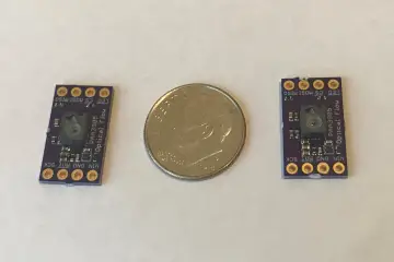
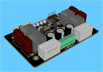
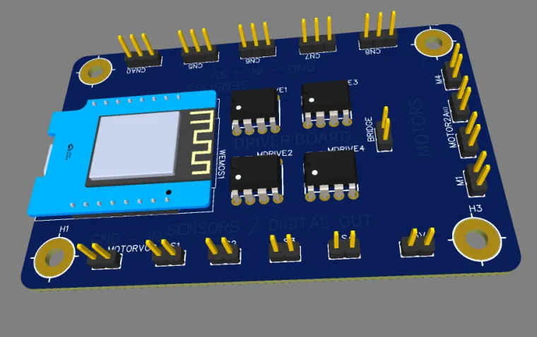
This is a super basic motor driver brain, meant for the Wemos D1 mini, it is capable of four sensor inputs, along with 4 output motors, 2 motors are connected to pins 1,2,3,4, along with having 4 adjustable pins 5,6,7,8, allowing for either 4 sensors, or two motors.
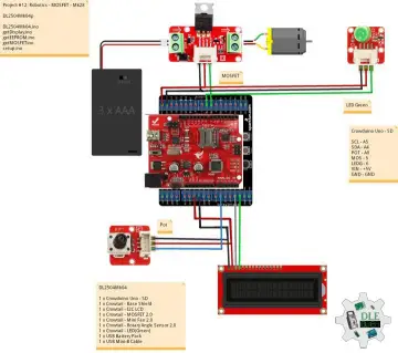
Pinout
The pinout is as follows (the silkscreen on the PCB should help with this),
D1 - Motor A1
D2 - Motor A2
D3 - Motor B1
D4 - Motor B2
D5 - Sensor 5/Motor C1
D6 - Sensor 6/Motor C2
D7 - Sensor 7/Motor D1
D8 - Sensor 8/Motor D2
A0 - Analogue Sensor 1
Compatability and ports
There is dupont connectors included on the board for simplicity with connecting. The wires are very commonly used around breadboards.
The original version of the PCB, and design used JST connectors, I have decided to go away from these, to keep costs down.
Structural
You might notice that this project doesn't have any structural elements attached, that is due to the flexible nature of the board, allowing for many different projects and uses.
When I build these robots I like to use the Open Robotic Platform, openroboticplatform.com
Using the ORP guidelines, many different projects are able to be accomplished. There is many different connectors for different sensors, and motors, such as the TT gearbox motors.
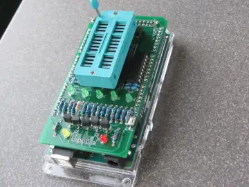
Assembly
Step 1 - Arrange all the components you need, such as the PCB, motor driver, JST connectors, and the Wemos.
Step 2 - Place them all into the holes on the PCB, note the orientation of the JST connectors based on the silkscreen.
Step 3 - Cover in a peice of thin cardboard, and flip so that the cardboard is on the bottom, and the pins are facing up.
Step 4 - Carefully solder all of the components onto the board, starting with the motor driver, then moving to the JST connectors, and finally the Wemos.
Sidenote: When I solder on boards, like the Wemos, I like to put female headers instead, and put male headers on the board, so I can easily remove the board from the PCB.
Step 5 - Programming the Wemos. Since I don't want to veer off topic into the programming of the Wemos, there is an excellent instructable here: https://www.instructables.com/Wemos-ESP8266-Getting-Started-Guide-Wemos-101/ which goes into better detail as to how to get started with programming the Wemos. Everyone starts from the blink sketch, and you should too. Then move onto the harder stuff.
Power
There is two different connectors on the board, one for 5V for the Wemos, and sensors. And another for the motors, the power to the motors can either share the same 5V (by bridging to pins labelled, "bridge", or have more or less power, depending on your needs, the chips can support up to 30v of power, just ensure that the motors can handle that much power, it can also go down to 1.3v, allowing for slower rotation of the motors.
Conclusion
The size of this board is exactly the same as a normal credit/ID card, which makes it easier to design for CAD.
This project is still a work-in-progress, and I hope to see a community flourish around this board.
I also need a name for this board, and I would be open to hearing your suggestions in the comments.
Have a great day!