

Story
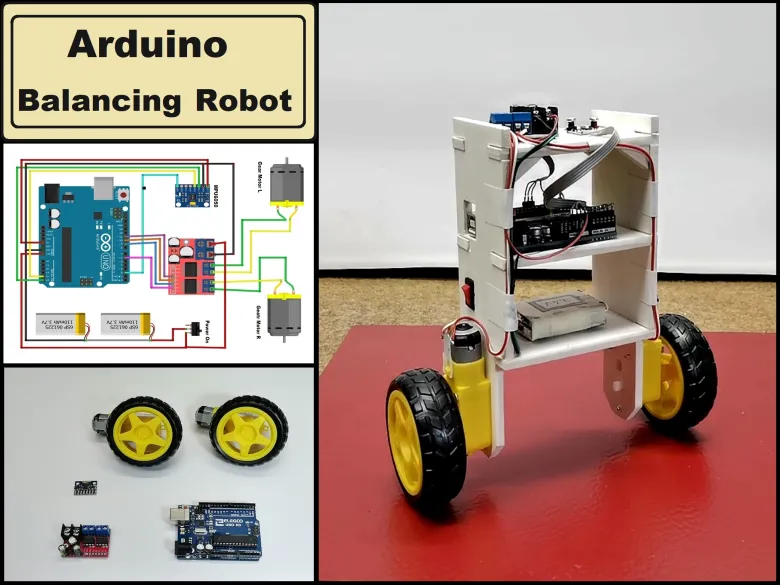
Self Balancing Robot is device that can balance itself from falling to the ground. Its function is to maintain balance using the motor’s axis movement of the wheels and body. There are several types of self-balancing robots, and in this particular case I will present you a way to make a Two-Wheeled Balancing Robot. Actually, I made this robot together with one of my students and it is a high school graduation project. This is the simplest type of balancing robot and only requires a few components to build.
Detailed video description at: https://youtu.be/aVi6dJwe6Y0
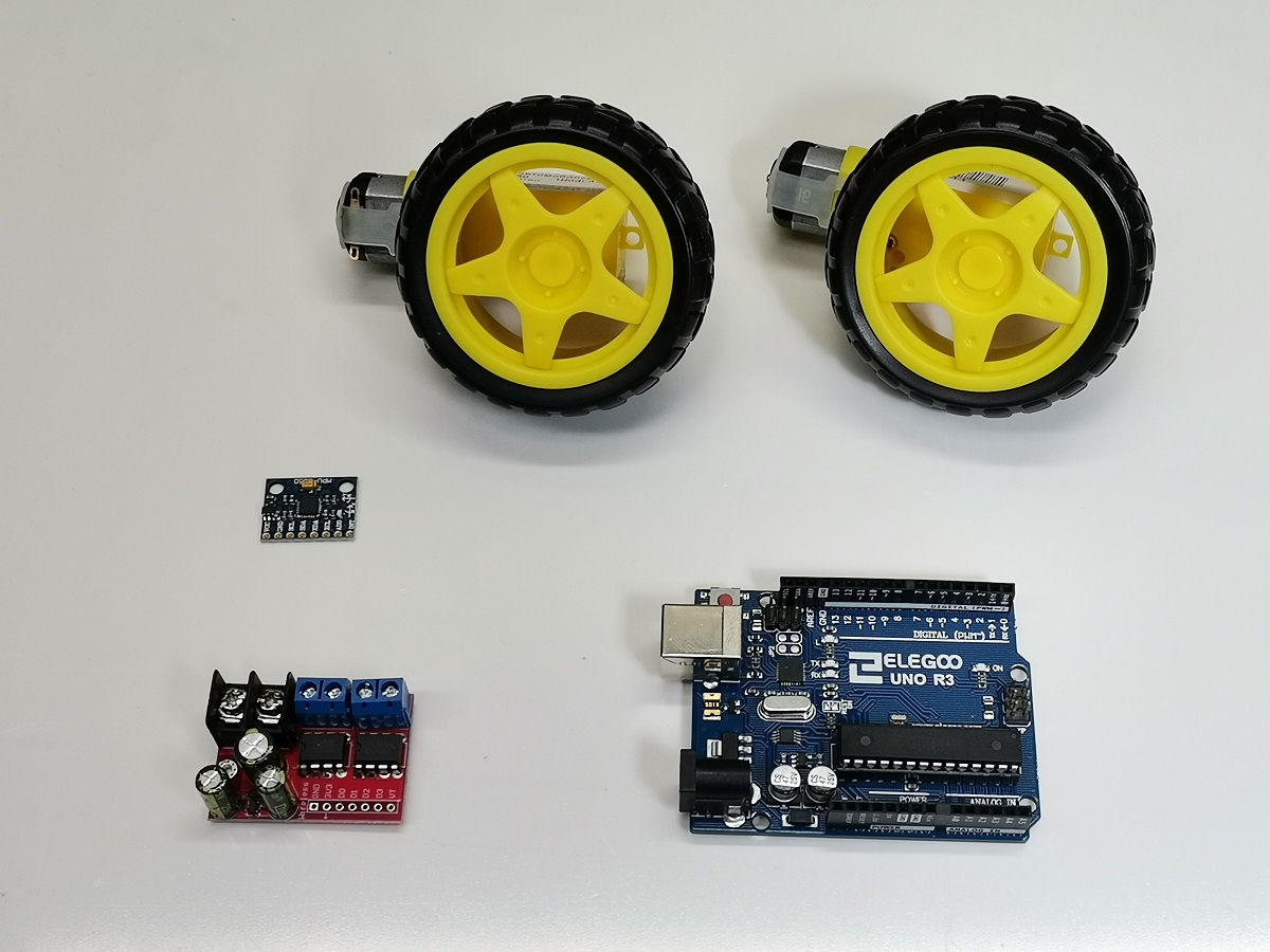
First, let's explain the components used and their functions.
- MPU6050 Accelerometer and Gyroscope sensor with Micro Electro Mechanical System(MEMS) technology, which is used to detect angle of tilt or inclination along the X, Y and Z axes.
- The information from this sensor is transmitted to a microcontroller, and in our case it is an Arduino Uno board. This board is the brain of the robot, processes the sensor data and determines the actions needed to keep the robot upright.
- Processed data from the Arduino is sent to the motor driver board, which in our case is the L298N 5AD type. A motor driver circuit controls the direction and speed of the motors.
- This robot uses two DC motors, each connected to a wheel. These motors adjust the speed of the wheels to correct the robot’s tilt.
- and power source, specifically two Lithium batteries connected in series wich provides energy to the motors and electronics. All components are mounted on a suitable supporting structure made of 5mm thick PVC board.
Now, let's briefly explain the working principle: The accelerometer gives a measure of the robot’s orientation relative to gravity, and the gyroscope detects the rate of tilt. The Arduino uses a PID (Proportional, Integral, Derivative) controller to process the data from the sensors.
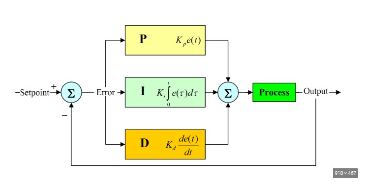
The PID controller calculates the necessary speed and direction adjustments needed to maintain the robot’s balance. If the robot tilts forward, the motors spin faster to move the robot forward and prevent a fall. If it tilts backward, the motors move the robot backward to regain balance. As the robot detects an imbalance, it compensates by adjusting the wheel speed, shifting its center of mass, or moving forward or backward to maintain its position.
A few words about the Arduino code. The method of installing the code has been described many times before, so now I will only focus on the modifications that need to be made individually for each case due to the different characteristics of the components used, as well as the method of their placement.
Now comes the fun part, which is customizing the code specifically for our built device. Depending on the layout of the components, the center of gravity of the robot changes, and also each MPU6050 board has minimal differences that need to be compensated for in part of the code. If we look at the code in more detail, we will see that there is a place where the Gyro offset is set.

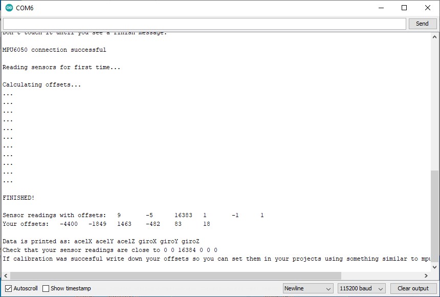
In this part of the code, errors are corrected during the manufacturing of the MPU6050 chip. For each individual chip, these values are different. Their value is determined using Arduino code made specifically for this purpose and you can download it at the end of this text.
Next, we need to move on to setting the Accelerometer. In the "double setpoint' line, we need to put a value that corresponds to our device.
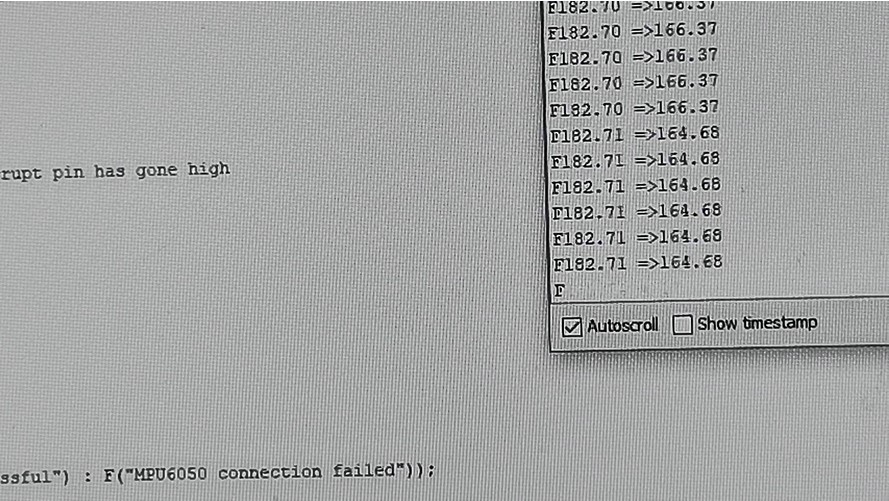
To obtain this value, we need to hold the robot in an ideal vertical position, perpendicular to the surface, and read the required value on the serial monitor. In my case, it is about 182.
Finally, we need to experimentally determine the values of Kp, Kd, and Ki, needed for PID control.

For this purpose we set all three values to zero. Now we put some value for Kp and perform testing. Too little Kp will make robot fall over. Too much Kp will make the robot go back and forth wildly. A good Kp will make the robot go slightly back and forth. Next we need to set Kd. A gooD Kd value will lessen the oscilation until the robot is almost steady, and will keep the robot standing. Lastly set the Ki. The correct Ki value will shorten the time it takes for the robot to stabilize. I want to emphasize that the surface needs to be rough enough to increase the friction between it and the wheels.
And finally a short conclusion. This is a relatively simple, visually effective balancing robot project that only requires 3 components to make. However, its setup, although it can be time-consuming, is still a lot of fun trying to get the robot to stand steadily on its "own feet". Just to mention that we created this project together with my students as a final high school exam.