Story
ARDUINO LCD 1602 SHIELD + KEYBOARD
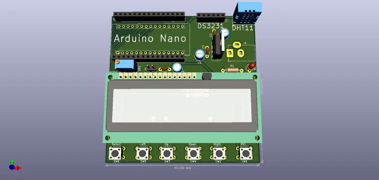
The LCD1602 shield can be mounted together with an Arduino Nano development board to add an LCD display and keyboard.
After installing the shield, you can upload a code to test its functionality. It is recommended that the pins used by the LCD and buttons not be used by other components, such as sensors, so that there may be interference.
LCD pins used:
? RS - digital pin 8;
? EN - digital pin 9;
? D7 - digital pin 7;
? D6 - digital pin 6;
? D5 - digital pin 5;
? D4 - digital pin 4.
The buttons use the analog pin A0.
If you have loaded the code on the development board and the characters are not displayed properly, the brightness of the LCD may not be appropriate. This can be adjusted by means of the blue potentiometer installed on the shield.
The shield is designed for multiple needs and the light turns on automatically if pin D10 is not used. Set the D10 output / low pin to turn off the light, and to turn it on set the pin as input or do not declare it at all. Do not use pin D10 as output / high or pwm as short in shield.
The ranges for the analog keyboard differ. You can determine them using the example in the link. You can use the example here: http://openhardware.gridshield.net/home/lcd-keypad-shield-test
Description
The shield contains:
- a 1602 LCD display (2 rows x 16 characters) compatible with HD44780;
- 6 buttons;
- a DS3231 RTC module;
- a DHT11 module;
- a 5V stabilizing source.
The pins used are 8 in number, according to the attached diagram: pins 4, 5, 6, 7, 8, 9, 10 for the LCD and pin A0 to read the buttons.
The buttons are read using the ADC device, which generates different voltages by pressing them. The generated values ??are approximately equal to: 30, 150, 360, 535, 760.
The contrast of the LCD can be adjusted using the potentiometer.
Bill of materials available in the download section.
Have fun with it and share your projects!


