Add to cart
Board Type : GerberFile :
Layer : Dimensions :
PCB Qty :
Different PCB Design
PCB Thickness : PCB Color :
Surface Finish : Castellated Hole :
Copper Weight : 1 oz Production Time :
Total: US $
Elecrow community is a shared platform and we are not responsible for any design issues.

PCB Assembly

PCBA Qty: BomFile:
NO. OF UNIQUE PARTS: NO. of Components:
Assembly Cost: US $
Elecrow community is a shared platform and we are not responsible for any design issues.
Add to cart
3dPrintingFile : Size :
Unit : Volumn :
3D Printing Qty : Material :
Total: US $12.99
Elecrow community is a shared platform and we are not responsible for any design issues.
Add to cart
Acrylic Type : AcrylicFile :
Dimensions: Engrave:
Acrylic Qty :
Acrylic Thickness:
Acrylic Color:
Total: US $12.99
Elecrow community is a shared platform and we are not responsible for any design issues.
Add to cart
CNC Milling File : Size:
Unit: Volumn:
CNC Milling Qty : Material:
Type of Aluminum: Surface Finish:
Tolerance:
Surface Roughness:
Total: US $12.99
Elecrow community is a shared platform and we are not responsible for any design issues.
closed
user-img

cris

Published: Oct 05,2024

Anti-Freeze (Detector)

A circuit that suits for cold areas, to prevent the frost.

ccc ccc
Copyright Info

Attribution-ShareAlike (CC BY-SA)

Read More⇒
  254
  1
  0
cover-img
 
  • thumbnail-img
  • thumbnail-img
  • thumbnail-img
  • thumbnail-img
 

Hardware Components

  • UA747

    X 1 fenxiang
  • CD4028

    X 1 fenxiang

Tools, APP Software Used etc.

  • Kicad

Story

Anti-Freeze (Detector)

I present a circuit from an older electronic magazine, but maybe quite popular for some older people.

Attached to a car, in the vicinity of storage systems or warehouses, agricultural farms or animal husbandry, a device to signal the danger of frost is always welcome.

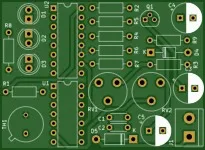
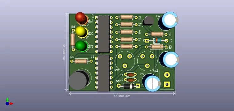
The presented scheme uses as probe a NTC thermistor (TH1) of 10kohm and as warning elements three LEDs: green for temperatures above 3..4 * C, yellow for 1 ... 2 * C when there is a possibility of frost and red for signaling 0 * C and below. The control functions are performed by two UA747 comparators, with hysteresis. The semi-adjustable RV1 and RV2 are used to adjust the 3 thresholds, signaling the LEDs connected to the 2-3-15 outputs of the CD4028 (U2). Below 2 * C, RV2 is adjusted so that output 2 of U2 (yellow LED) is active, and below 0 * C the same setting is made for RV1. A 12V power supply would be needed.

BOM:

"C1" "100nF"

"C2" "100nF"

"C3" "10uF"

"C4" "10uF"

"C5" "100uF"

"D1" "Red"

"D2" "Yellow"

"D3" "Green"

"D4" "10V"

"D5" "1N4007"

"J1" "12V"

"Q1" "2N3904"

"R1" "33k"

"R2" "3k3"

"R3" "3k3"

"R4" "1M"

"R5" "3k3"

"R6" "3k3"

"R7" "1M"

"R8" "220"

"R9" "330"

"RV1" "22k"

"RV2" "22k"

"TH1" "10k_NTC"

"U1" "UA747"

"U2" "4028


P.S. I'm not the original author of this circuit, I just drew it.

Schematic and Layout
user-img

cris

+ Follow

Topic

View All
  • Comments( 0 )
  • Like( 1 )
/1000
Upload a photo:
You can only upload 1 files in total. Each file cannot exceed 2MB. Supports JPG, JPEG, GIF, PNG, BMP

You May Also Like

View All