Story
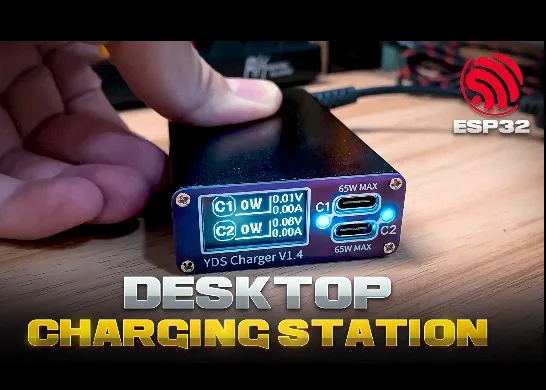
Four-way Desktop Smart Charging Station
Project Overview
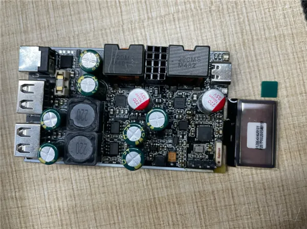
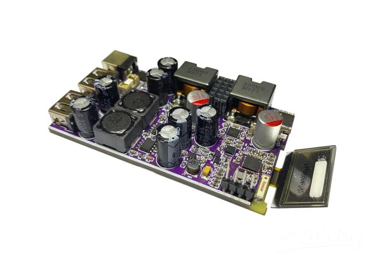
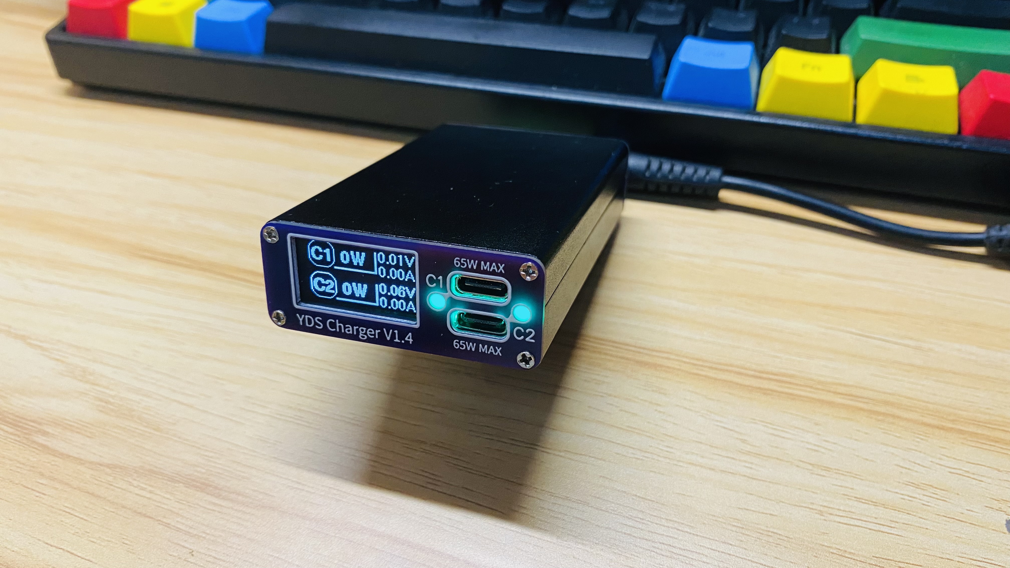
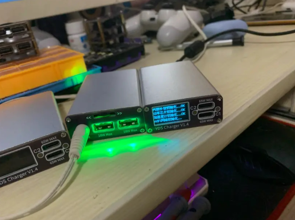
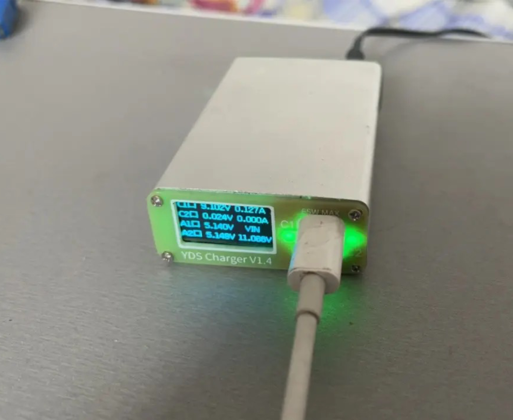
This project aims to create a practical, intelligent multi-channel desktop charger. The design and implementation are open source, encouraging enthusiasts to replicate, improve, and sell a limited number of finished products or kits at a fair price, promoting the spirit of open-source collaboration.
Description
Hardware
- Components: Upper board, lower board, front panel, rear panel
- Files: Gerber files, schematic source files, schematic PDF, coordinate files, BOM file
Firmware
- Components: ESP32C3FN4 firmware and tools, drivers, burning software
Software
- Development Environment: esp-idf-4.4
Structure
- Files: Circuit board and shell assembly files (SolidWorks 2022)
Documentation
- Manuals: Project-related documents
Data Description
The project includes all necessary files for replication:
- Gerber files for all boards (upper, lower, front panel, rear panel)
- Schematic source files
- README file
- Firmware and bootloader
- Structural design files
- Manuals and drivers
- Source code project folder
Project Introduction
Hardware Selection
-
- Control MCU: ESP32C3FN4
- Features: WiFi, Bluetooth, built-in 4M FLASH
- C-Port Power: Zhirong SW3526
- Features: Multiple fast charging protocols, integrated power tube, max 65W per channel
- A-Port Power: Ingenic IP6525T
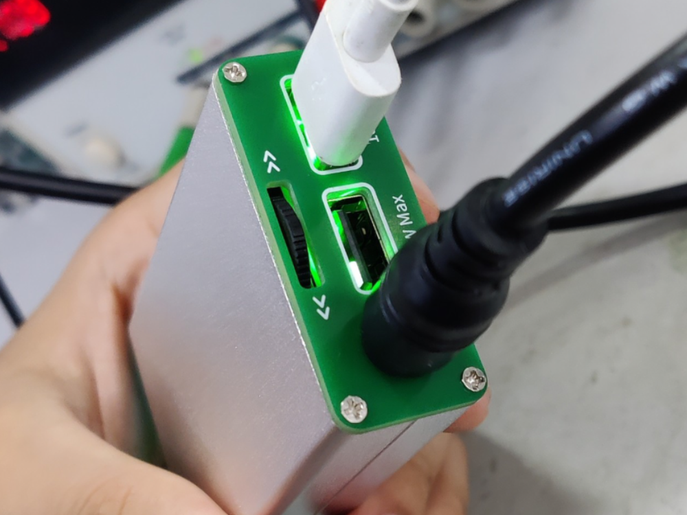
- Features: Max 18W per channel
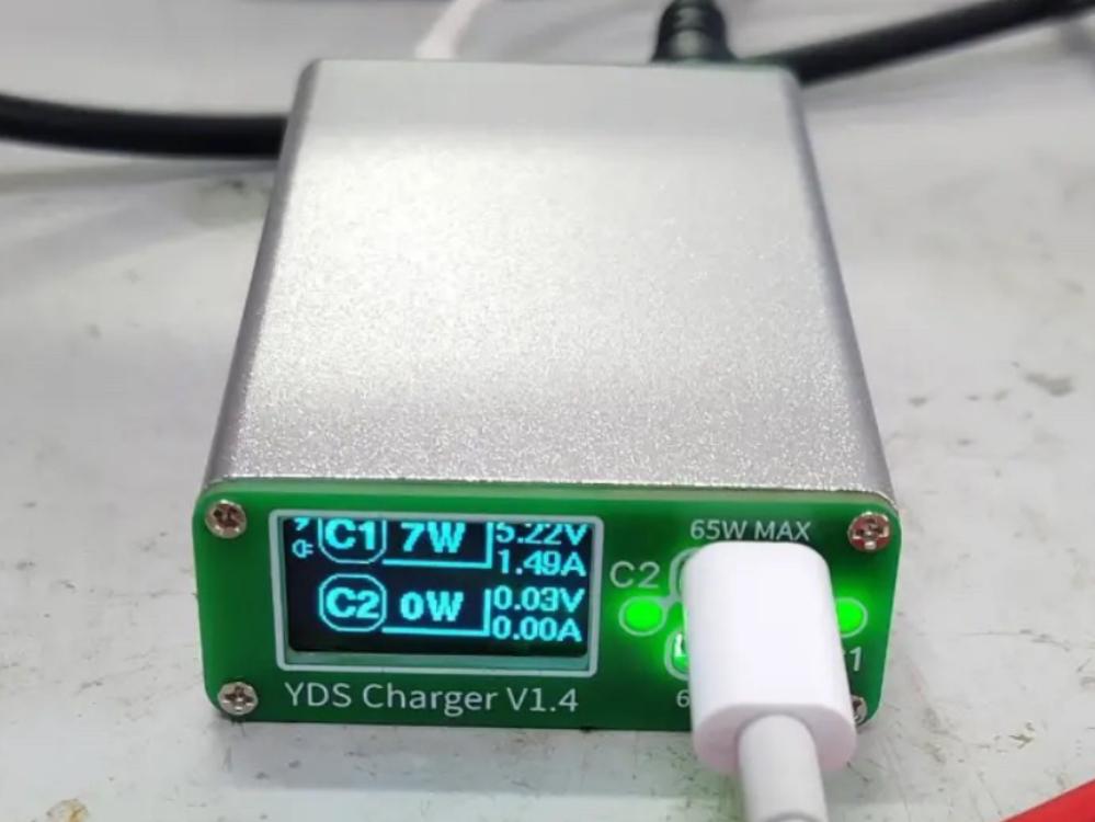
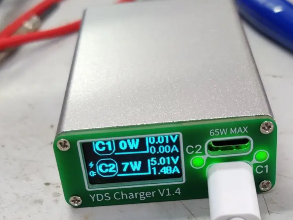
- Display: 0.96-inch OLED screen
- Protection Circuit: Anti-reverse connection, overcurrent protection, anti-ignition slow start
- Indicators: Four-way RGB lights for system status
- Sensor: LIS3DH accelerometer for vibration control or somatosensory operation
- Control MCU: ESP32C3FN4

Project Parameters
- Input Voltage: 10V-32V DC
- Input Power: >80W (144W at full load)
- Fast Charging Protocols:
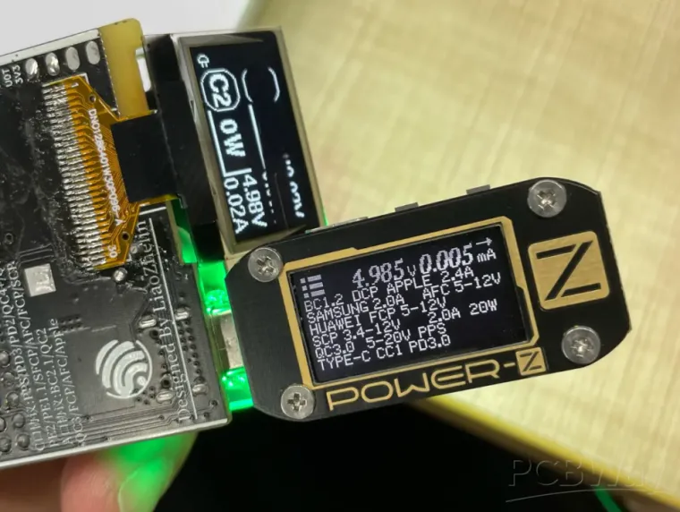
- C Port: PPS/PD3.0/PD2.0/QC4+/QC4/QC3.0/QC2.0/AFC/FCP/SCP/PE2.0/PE1.1/SFCP/BC2.1/Apple/Samsung
- A Port: DCP/QC2.0/QC3.0/FCP/AFC
- Output:
- C Port Voltage: 0.3-22V, Current: 0-3.3A
- A Port Voltage: 0.3-12V, Current: 0-3A
- PCB: 47*80 mm, 1.6mm thickness, four-layer
- Overall Size: 50x20x80 mm
Production Notes
- Testing: Ensure no short circuits or cold soldering before connecting to the computer.
- Heat Dissipation: Place heat conductive sheets on the power stage.
- Welding: Use steel mesh welding for cost-effective reflow soldering.
- Power On: Start with 5V power, then increase voltage after verifying output.
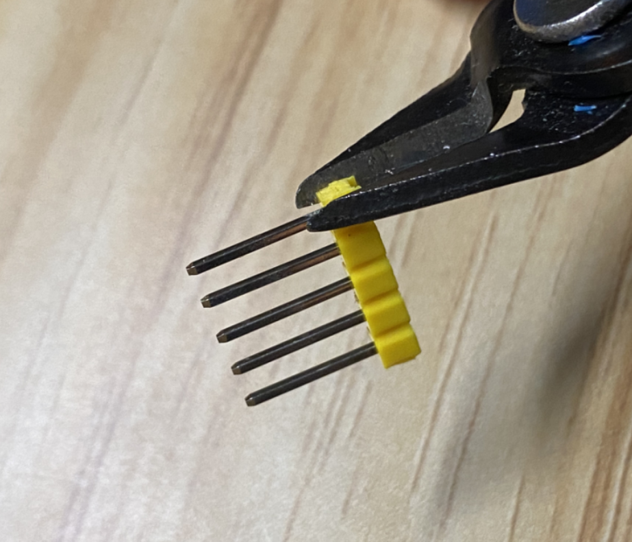
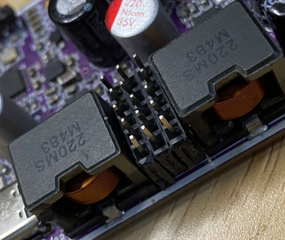
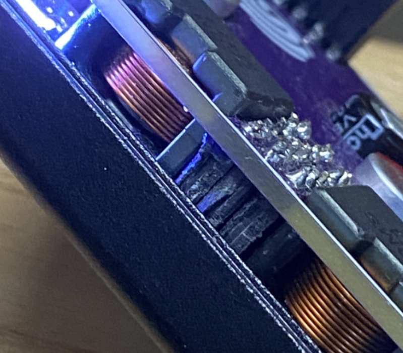
Firmware Burning Tutorial
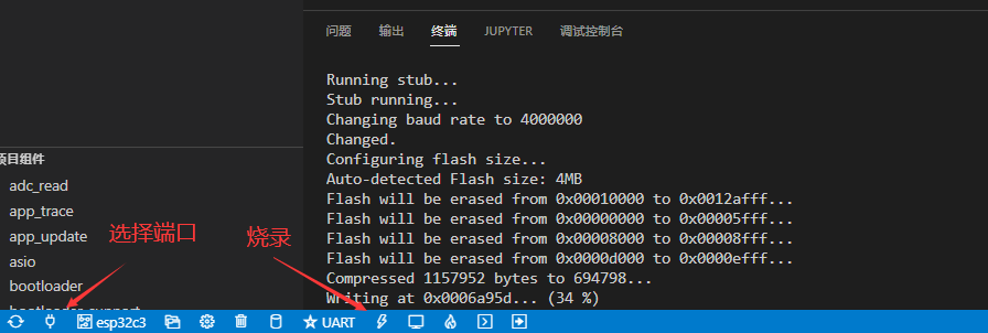
- Download Tool: Use flash_download_tool_3.9.2.
- Burning Steps:
- Connect device to computer via USB.
- Set download mode and addresses as shown in provided images.
- Burn firmware, then power cycle the device.
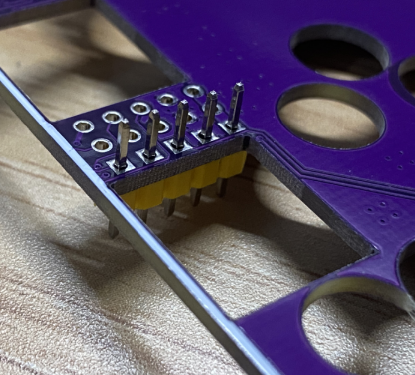
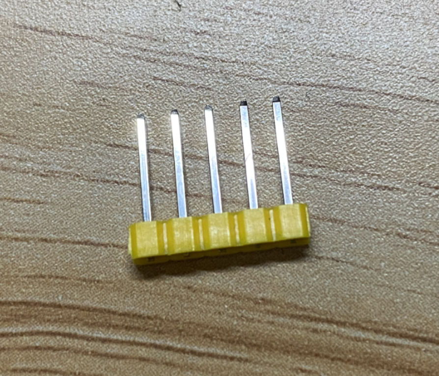
- BurnerBurner connection board
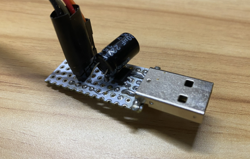
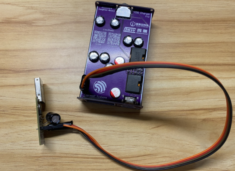
figure 1figure 2image 3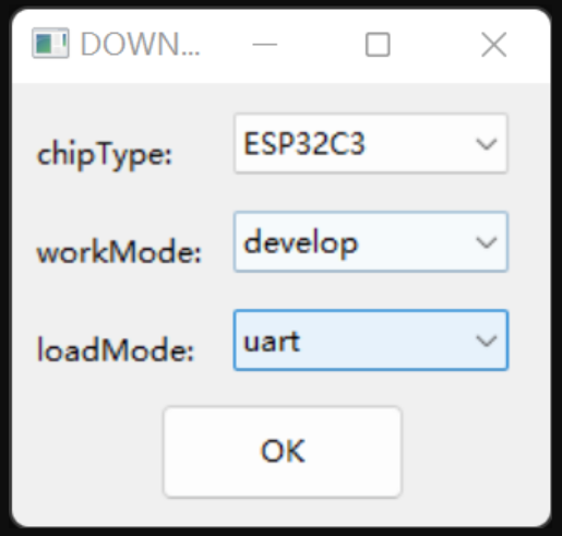
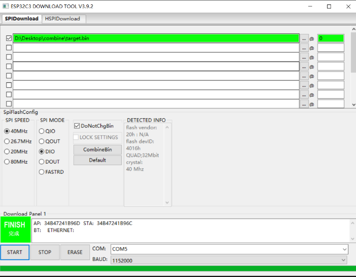
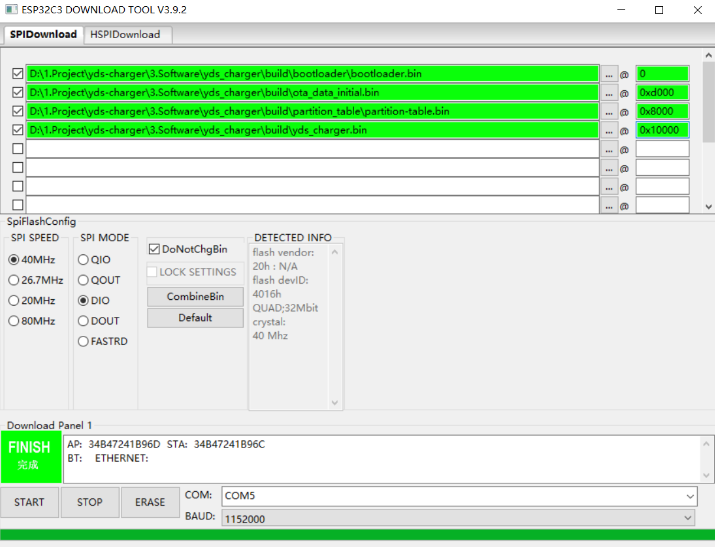
- OTA uses a ping-pong update partition of APP+OTA1+OTA2 (so that even if the power is cut off or the network is disconnected during the update, the device will not be bricked). After the initial burning and subsequent cover is closed, wireless updates can be used subsequently.
IDF Development
Environment Setup
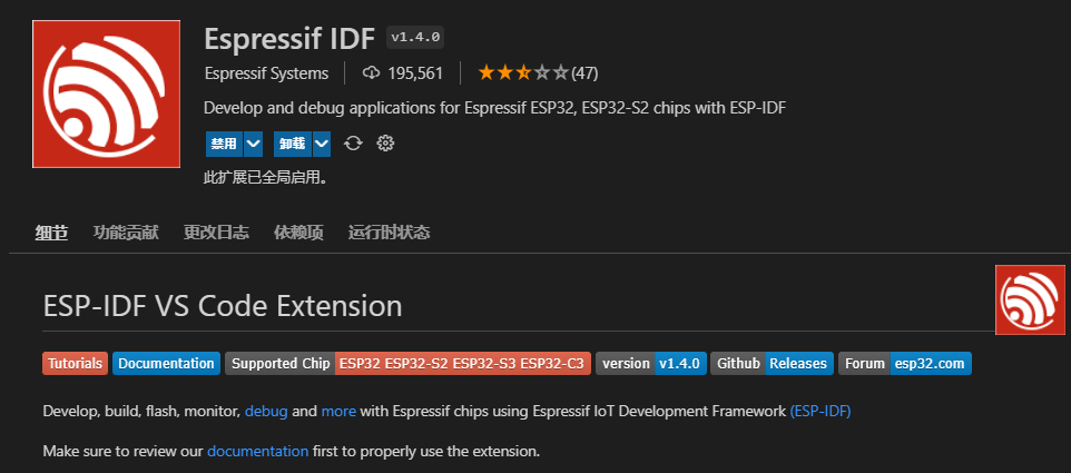
- VScode: Install VScode and ESP-IDF extension.
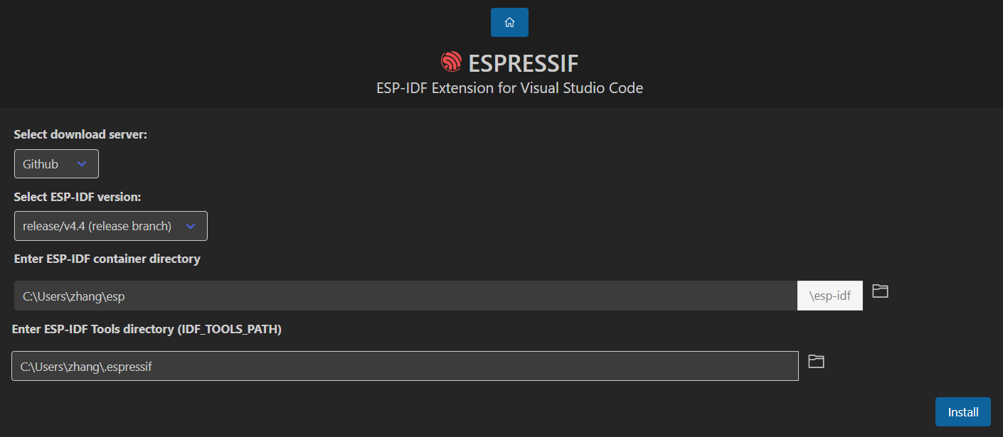
- Configuration: Use ADVANCED mode to set software source, IDF version (release/4.4), and paths.
- Tool Installation: Download and install ESP-IDF tools.
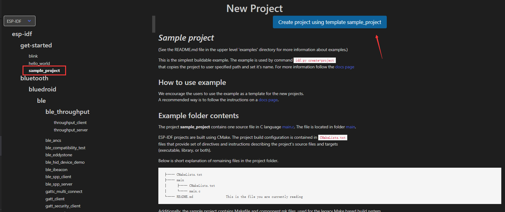
Importing and Verifying Project
- New Project: Create a new project to verify the setup.
- .vscode Folder: Copy necessary files for IDF and Vscode functionality.
- Compilation: Verify the environment by compiling a sample project.
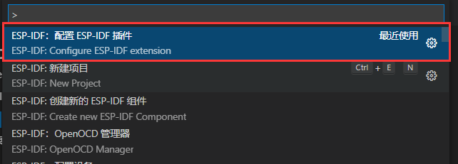
- After the plug-in is installed, press F1, find the option in the command Configure ESP-IDF extensionand click:
- Select ADVANCED mode to configure some options in detail:


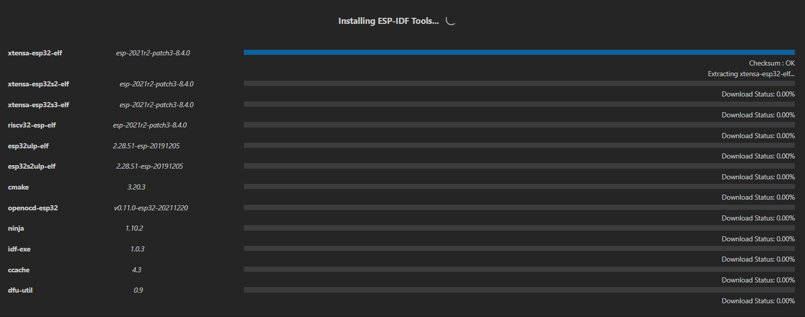




Function Development
- Completed:
- Remote network upgrade (OTA)
- WIFI network configuration
- Main interface display
- Fast charging protocol analysis
- RGB Indicator
- Voltage and current monitoring
- Overcurrent and reverse connection protection
- In Progress:
- Remote control charger four-port switch
- Accelerometer functions
- C port power limit
- OTA automatic detection version upgrade
- Planned:
- Computer CPU and memory usage display
- Weather display
- Fan number display
- Gravity rotating screen
- Bluetooth broadcast detection for automatic power on/off
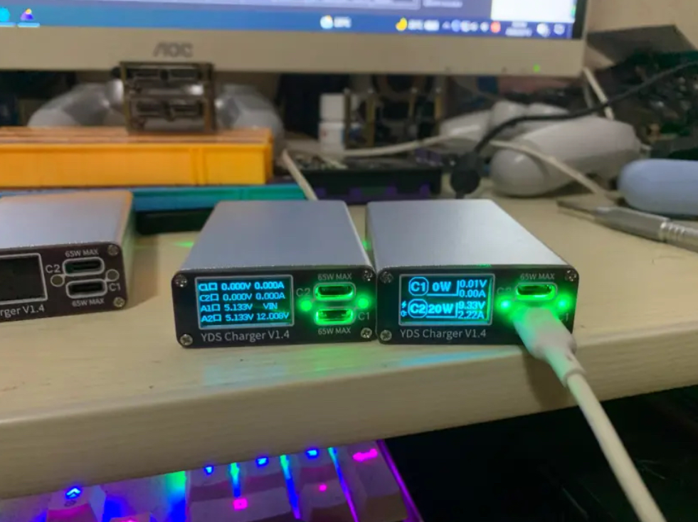
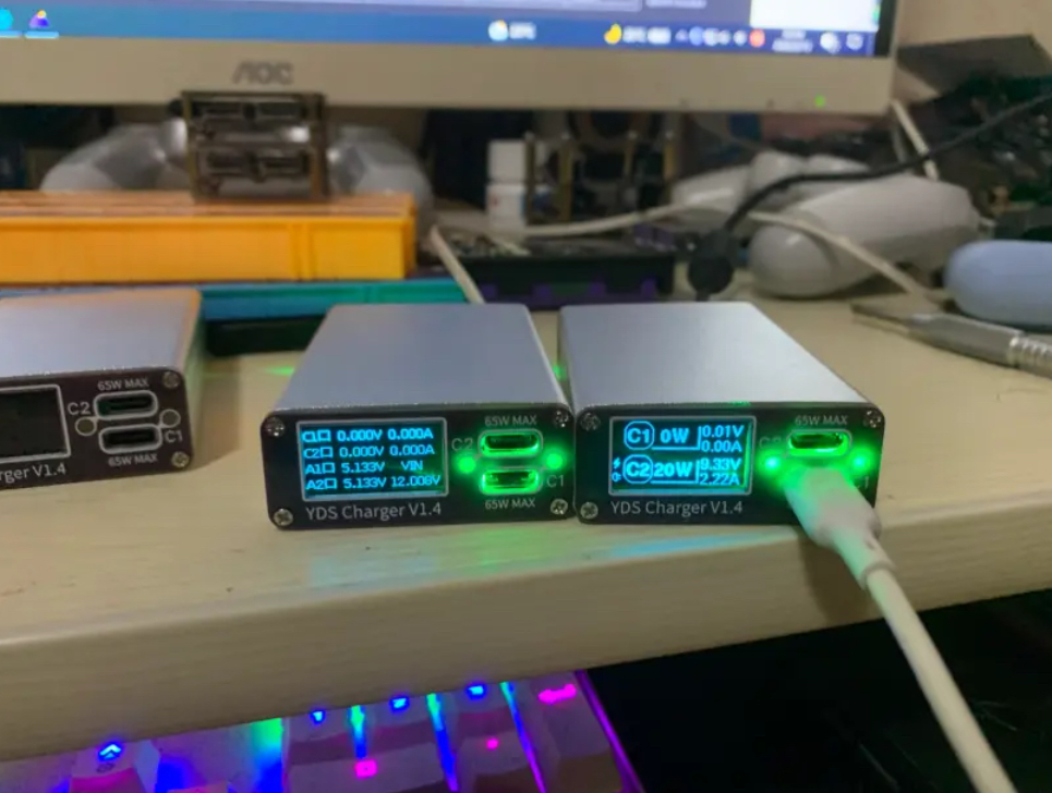
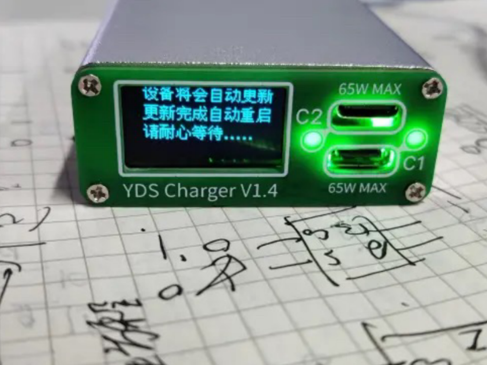
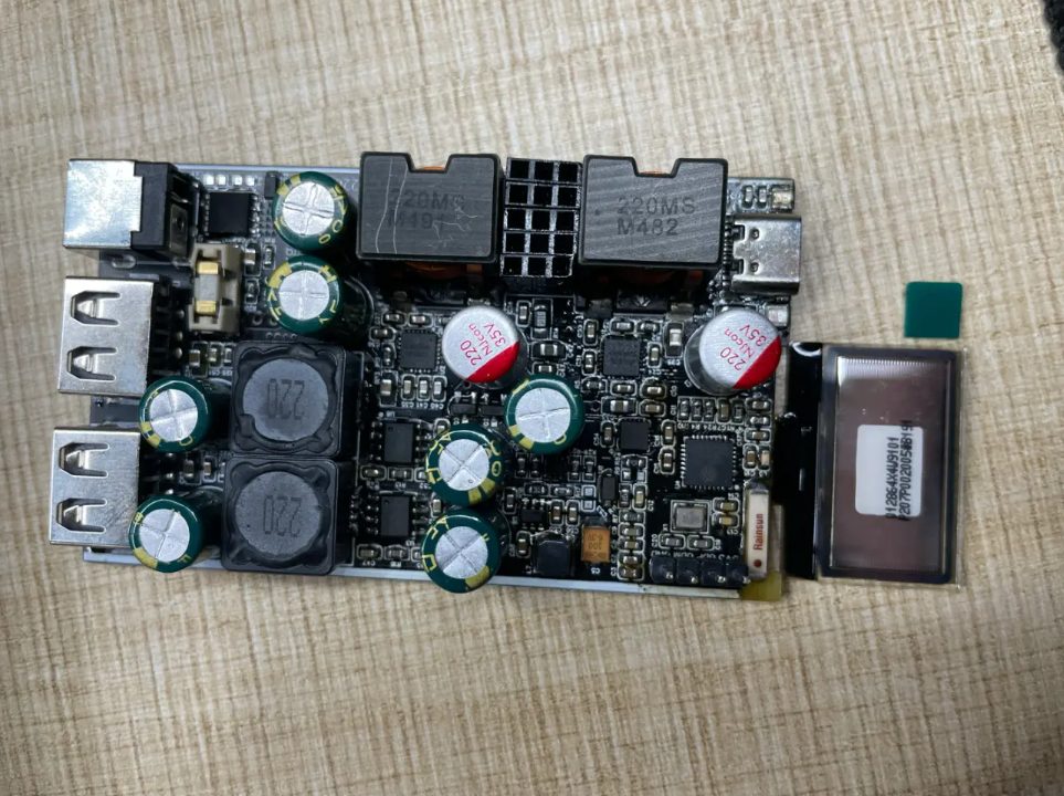
2022-6-16
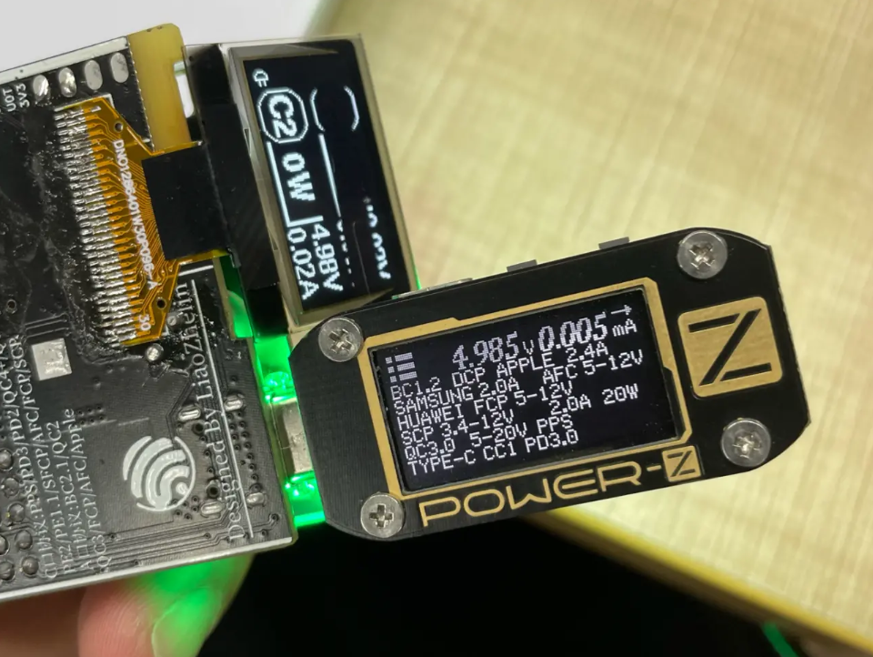
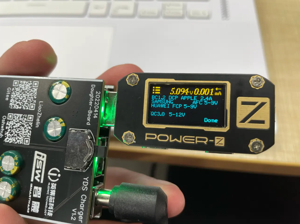
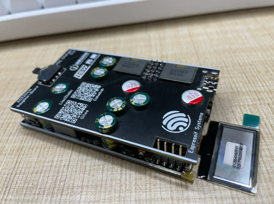
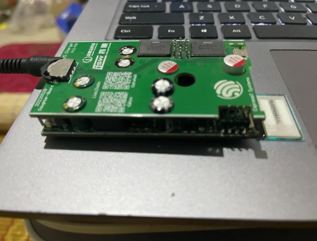
2022-6-18
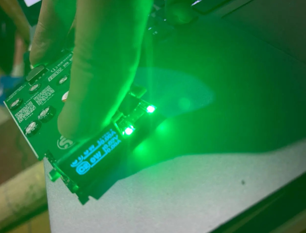
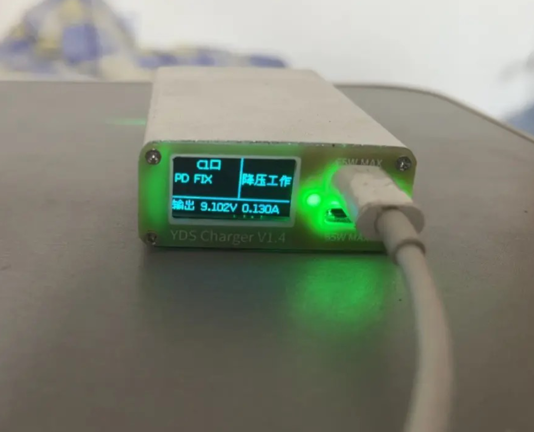
Conclusion
This project promotes an open-source environment, allowing enthusiasts to replicate, improve, and share their innovations. The provided resources and detailed instructions ensure accessibility and encourage collaboration. The finished products showcase the community's capability to develop practical and intelligent solutions.


