
Story
It can be very advantageous to create your own tools for your own work. They can better suit your needs compared to tools available for purchase. You can eliminate unnecessary features and only include the ones you need. As a result, you might be able to build tools for much less cost than buying them commercially.
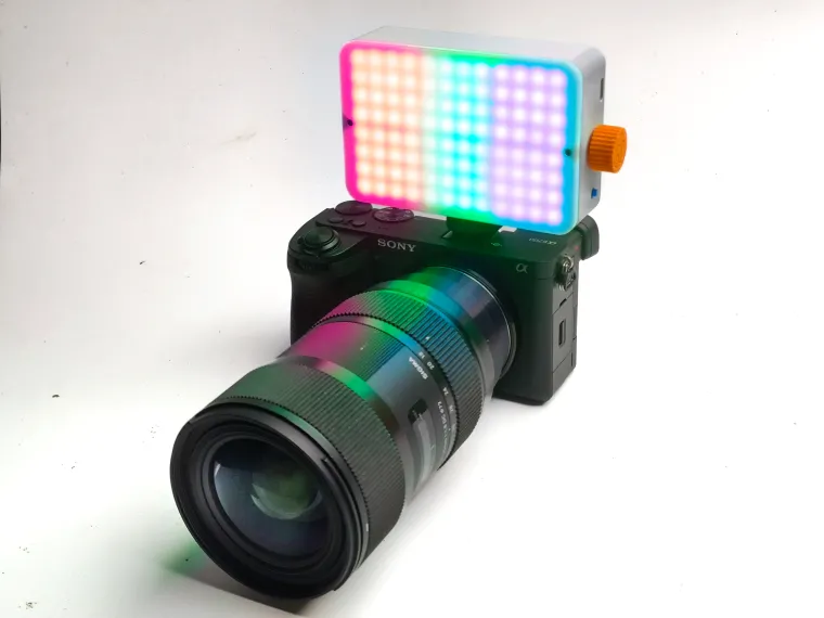
Apart from being a maker, I am also a videographer. So I needed an RGB video light. What I needed was an RGB light that was small, portable, magnetically attached to any metal surface, and could also accommodate accessories such as grids, diffusers, etc. but the lights with the kind of features I meant were costly. So I figured I could make one for a third of the cost. These requirements brought me to this project
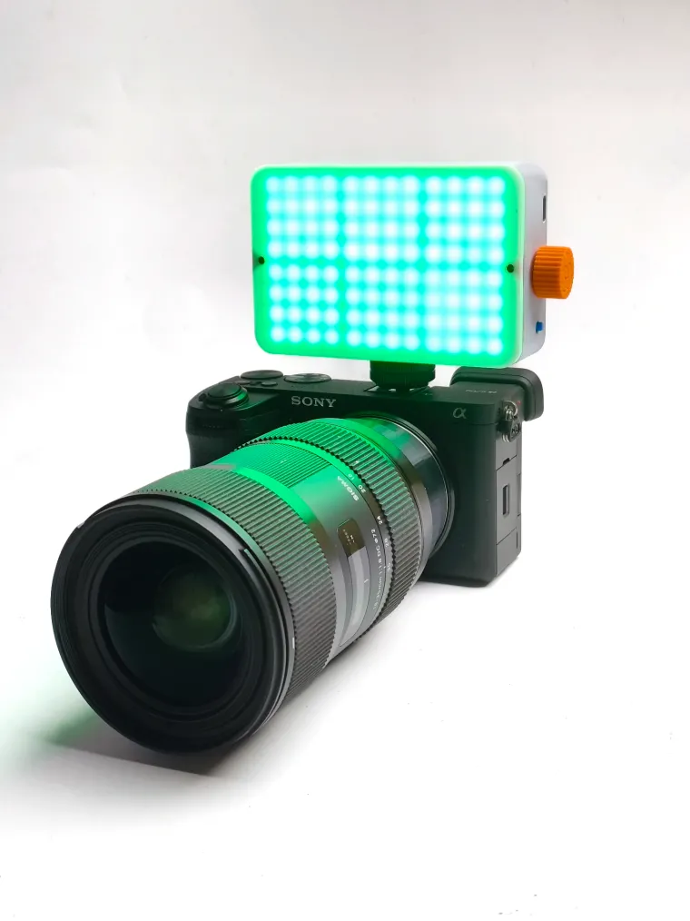
This small 20W RGB video light can be fully 3D printed and is very simple to operate. You can switch on the light by pressing the button on the side once. By rotating the encoder, we can cycle through the hue value. After pushing the encoder, we can switch to the brightness control mode. We can adjust the brightness of the LED by rotating the encoder. If we push the encoder button again, we can switch back to the hue control mode. It's a one-knob operation.
Additionally, I included a magnetically attachable diffuser for softening the LED light, and we can also attach a honeycomb grid on top of it to reduce the light spill. I included a 1/4-inch thread on the bottom to attach to a camera to make it easier to mount this light. I also added a powerful magnet on the back so you can easily attach it to any metallic surface. It is powered by a 5000mah battery which can run up to 2-3 hours. It is also rechargeable via USB-C. Battery status can be checked using the 4 LEDs on the back of the light. Now let's see how to build one yourself
**Wait a moment to load all GIFs on this Page
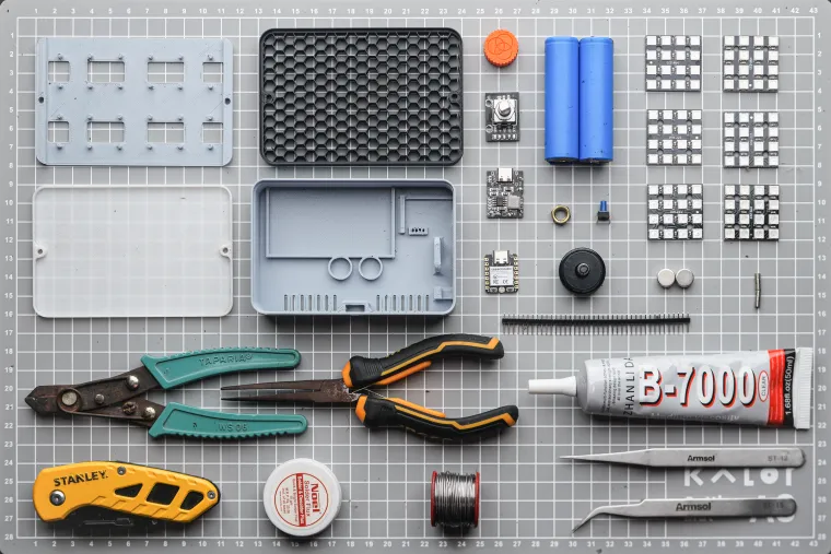
Supplies

**This image might not contain all the tools for this project due to space constraints.
Parts
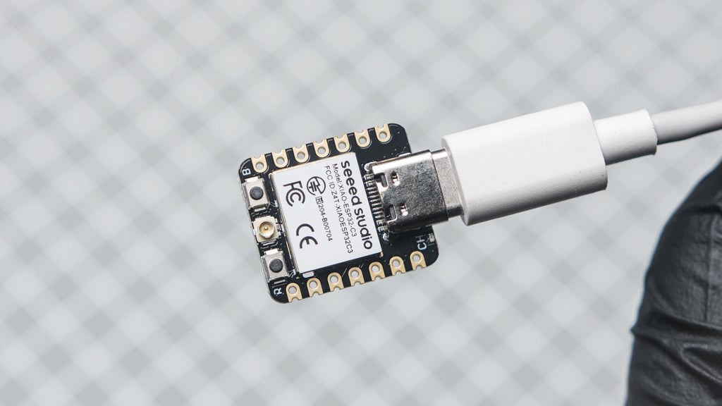
- Seeed Studio XIAO ESP32C3
- BMS + 5v booster module
- Rotary encoder
- Push Button Switch 6*6*7mm
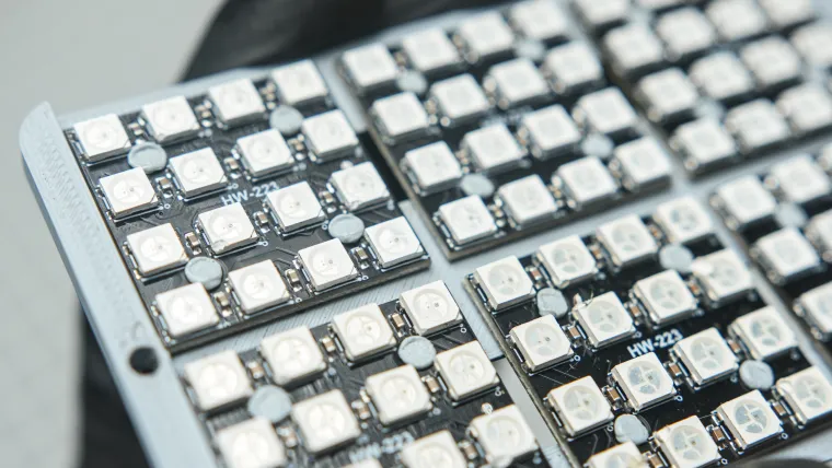
- 6 X WS2812B 4*4 16-Bit LED PCB
- Male header pins
- 1/4-20 HEX NUT
- 2* 10X5mm magnet
- 6* 3x3 mm magnet
- 1/4" Flash Hot Shoe Screw Adapter
- 30Awg wires
- 20Awg wires
- B-7000 Multi-Purpose Glue
- 2*2500mah 18650 battery (i used some recovered battery from old laptop)
- Kapton tape
Tools
- Soldering kit
- Wire cutter
- Third-Hand Soldering Tool
- Screwdriver
- Tweezer
- Nose Plier
- 3d printer (grey, white, orange PLA)
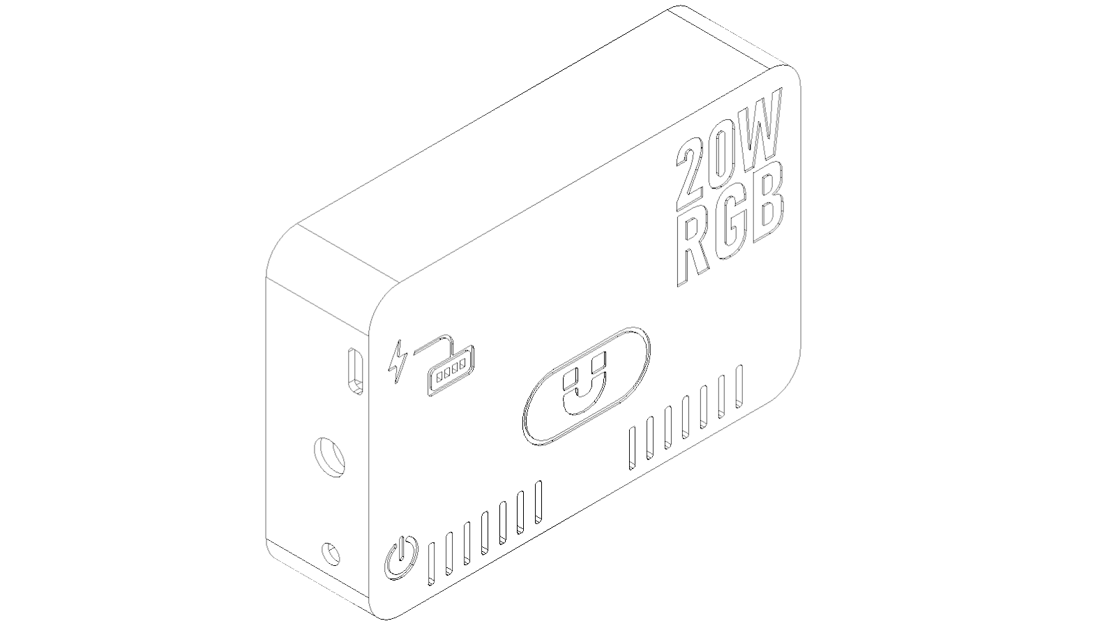
Step 1: Designing and 3D Printing
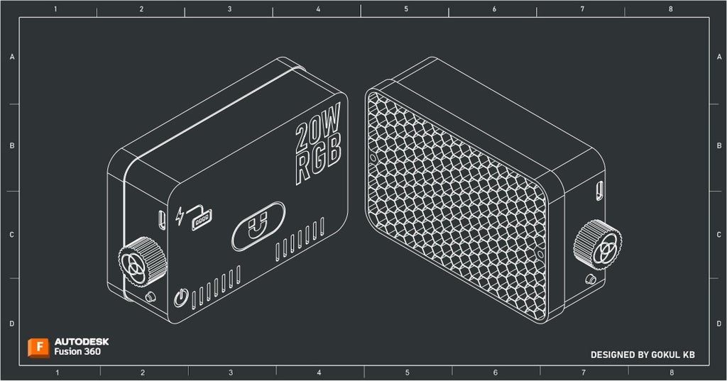
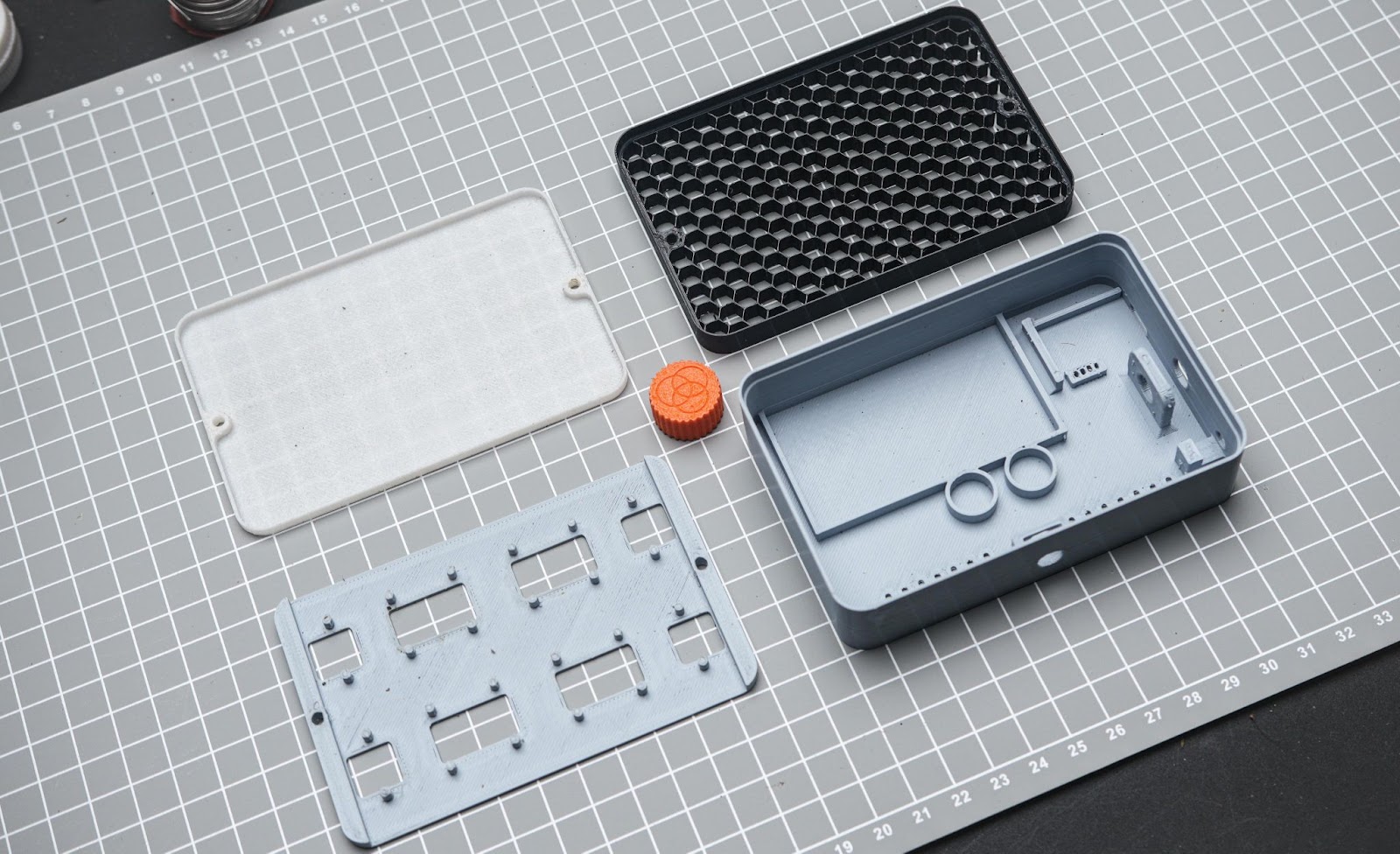
I Used Fusion 360 to plan and design this project. The main body is designed to hold the battery, BMS, encoder, magnets, power switch and the 1/4-inch thread. I also provide small gaps for ventilation on the backside.
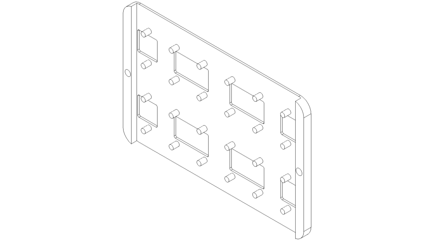
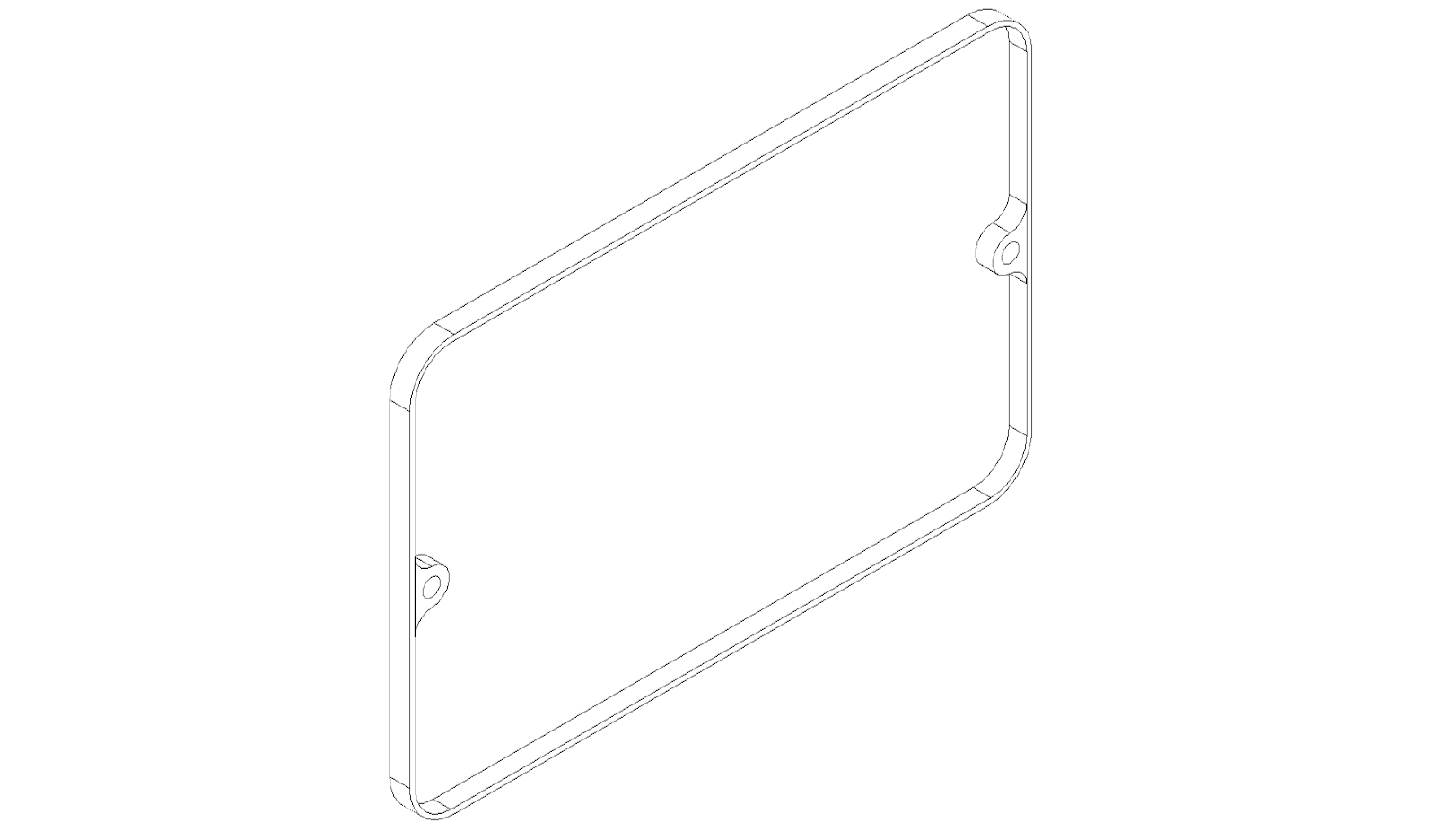
The led holder will help to hold the led PCB and magnet for the accessories
The LED diffuser is used to soften the LED output it also contains some magnets that help it to attach to the LED panel. also, it needs to be printed in white PLA or transparent
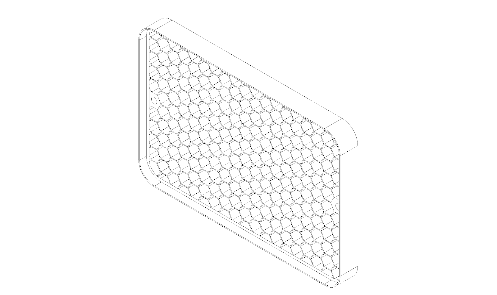
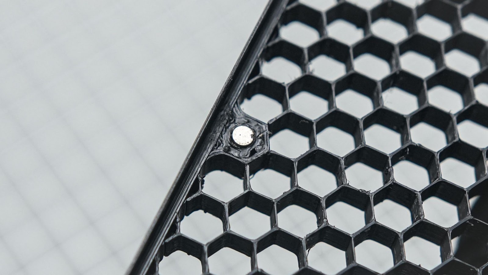
The honeycomb grid is designed to minimize light spill and features magnets for easy mounting on LED panels. It should be printed in black.
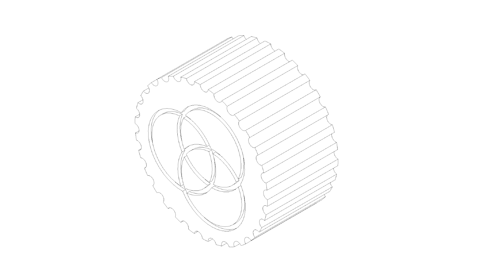
I also designed a knob for the encoder. included a three-ring RGB logo. I printed it in Orange PLA
After the designs, I exported all of the files to STL and 3d printed it. you can find all design files attached below
Attachments
Step 2: Wiring Diagram
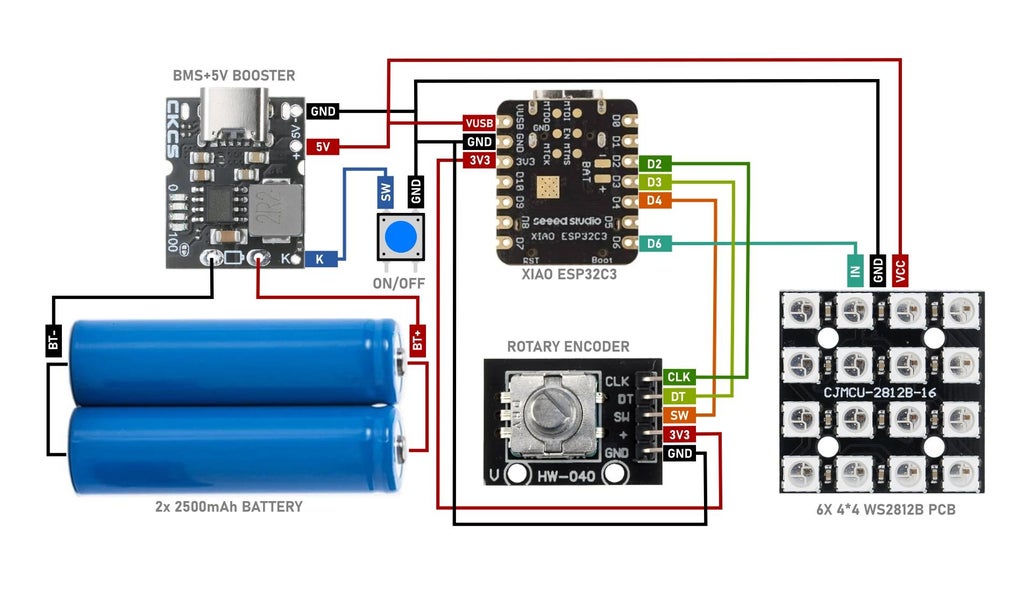
Please refer to the following wiring diagram when assembling the project. I used 30 AWG wires for the signals 20 AWG wires for the battery output and LED power cables. You can find the LED panel wiring diagram in the step below.
Step 3: Uploading Code to XIAO ESP32C3
I always like to upload the code to the microcontroller before assembly. I am using Arduino IDE to flash the code. follow these tutorials for setting up IDE for Seeed Studio XIAO ESP32C3 and learn more about this board
Please make sure Adafruit_NeoPixel.h and Encoder.h libraries are installed before compiling
I connected Xiao to a USB and flashed the program
Here you can have a quick look at the code I also attached the .ino file for this step
Attachments

Step 4: Mounting Magnets and 1/4 Inch Nut
4.1
We can start the assembly process by gluing the 10mm magnets into the 3D-printed slot. Apply some glue into the slot and place the magnets.
4.2
Place the 1/4 inch nut into the 3D printer slot and then glue it.
Step 5: Battery and BMS
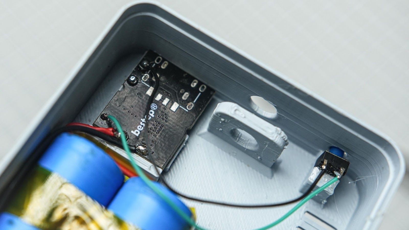
5.1
Ensure that the BMS is securely glued into place. Also, make sure to align the USB port with the 3D print.
5.2
Use Kapton tape to secure the batteries together.
5.3
I used this video to help me solder two batteries in parallel without a spot welder. I also soldered some external wires to the battery.
5.4
Be sure to use Kapton tape to cover the exposed battery contacts by tapping it.
5.5
Glue the battery into the 3D-printed slot.
5.6
Cut and solder the battery wires into the BMS.
5.7
Cut the two terminals of the push button, place the switch into the 3D printer slot and glue it
5.8
Connect the switch wires to the BMS
Step 6: Rotary Encoder
6.1
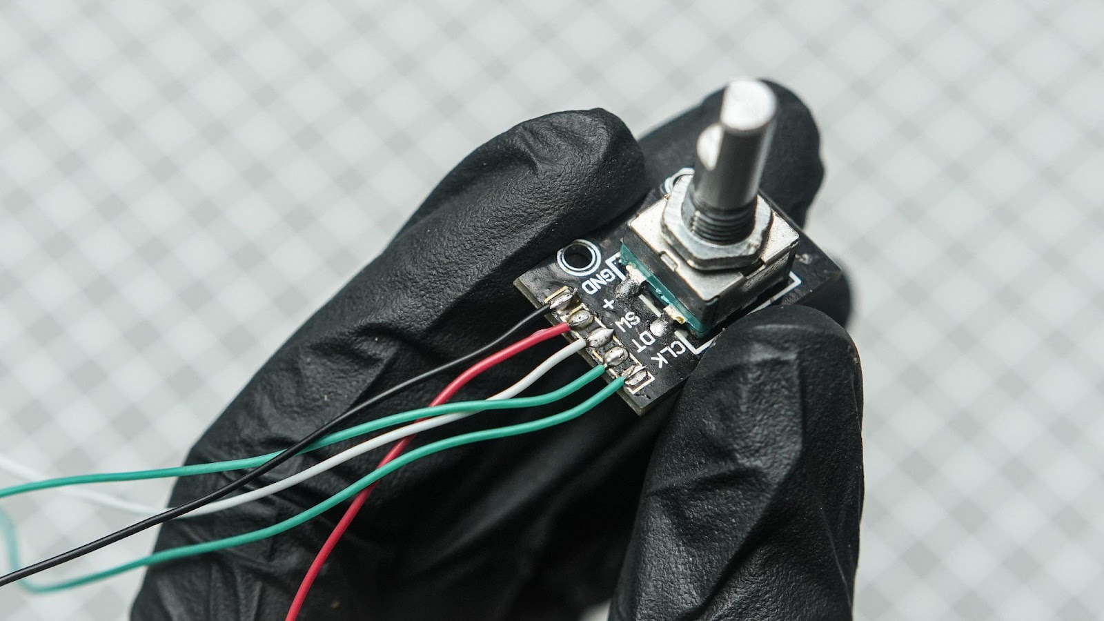
Solder 8 cm wires from all terminals of the encoder module.
6.2
Remove the nut from the encoder. Insert the encoder into the hole on the side by holding the nut with a nose plier between the encoder holder and the side wall. Tight to the net with the nose plier
6.3
Insert the 3D-printed knob
Step 7: XIAO ESP32C3 Wiring
7.1
Cut and solder encoder wires into the GPIOs of Xiao. Also, connect the power wires. Just follow the wiring diagram.
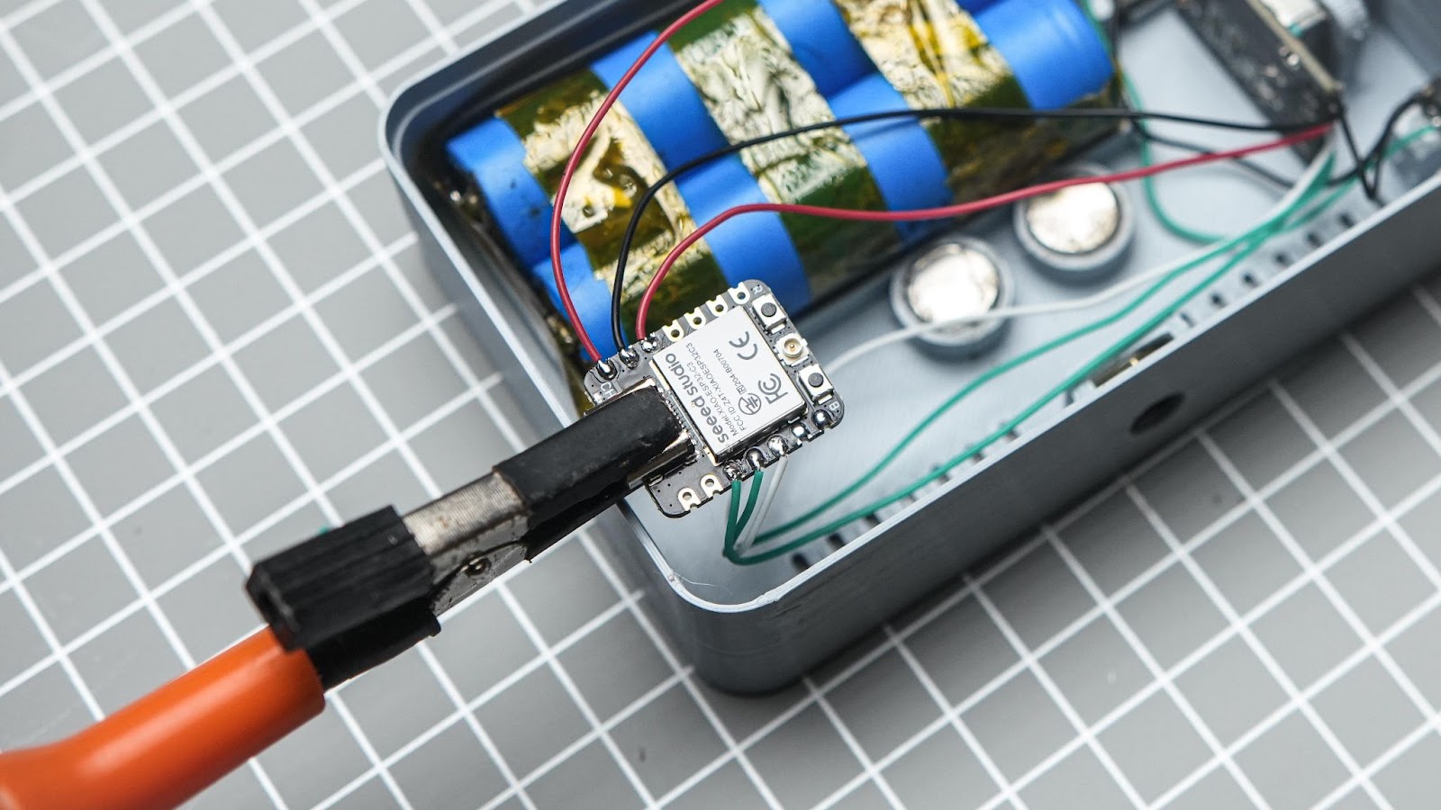
7.2
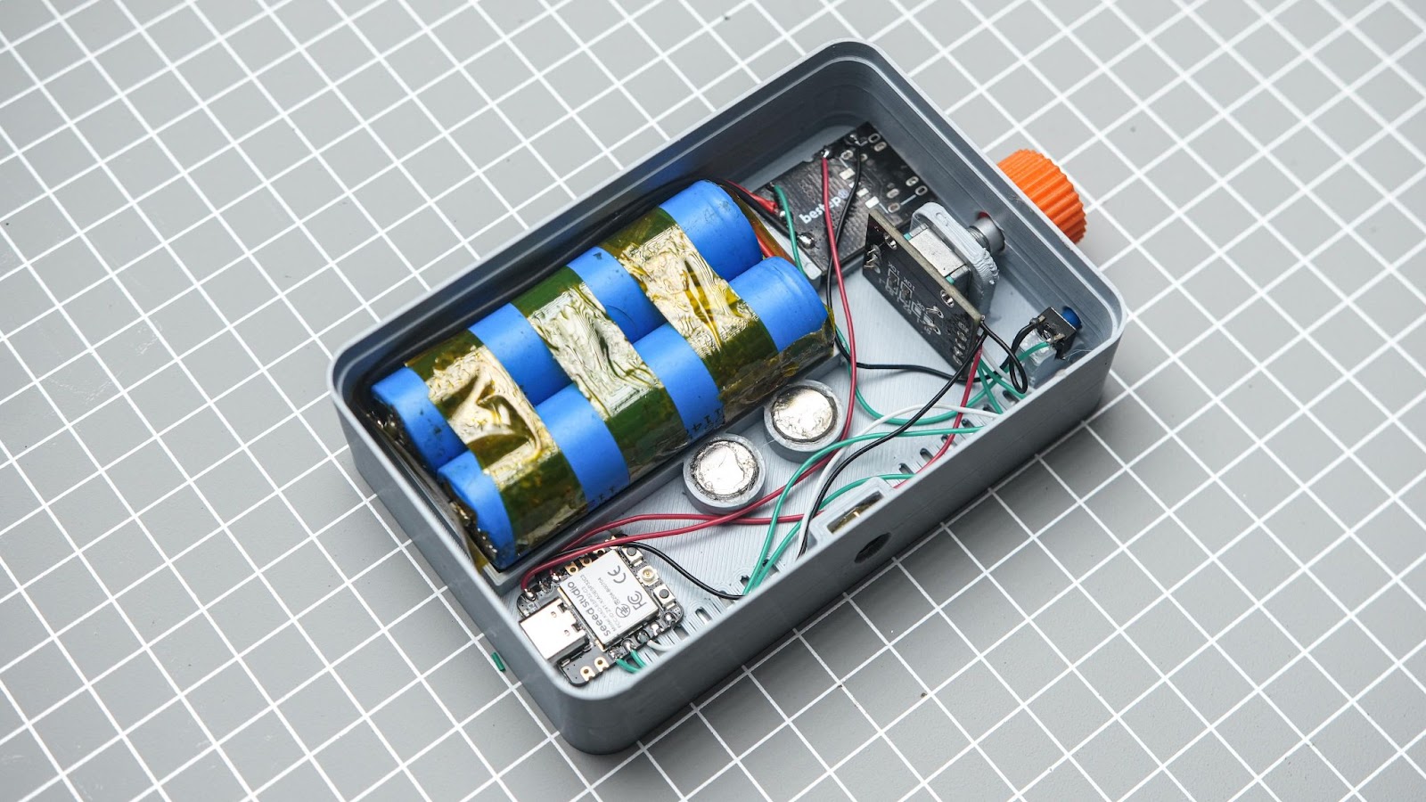
Glue XIAO ESP32C3 into the 3D print
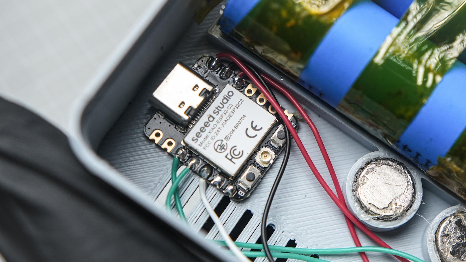
We just completed most of the wiring
Step 8: LED Panel Assembly
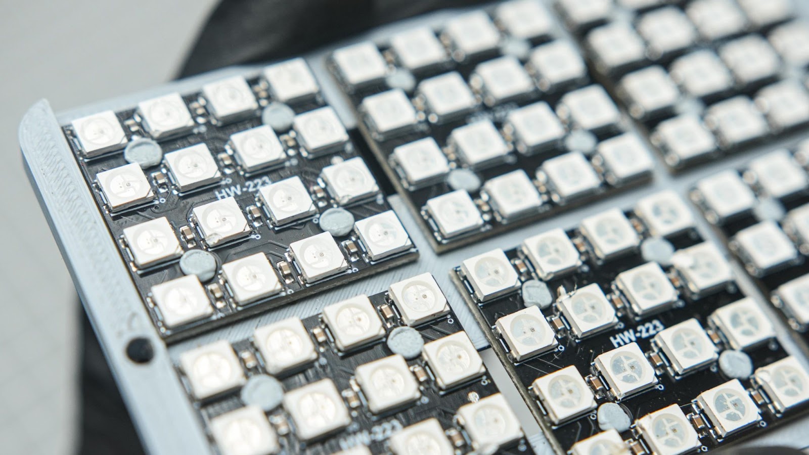
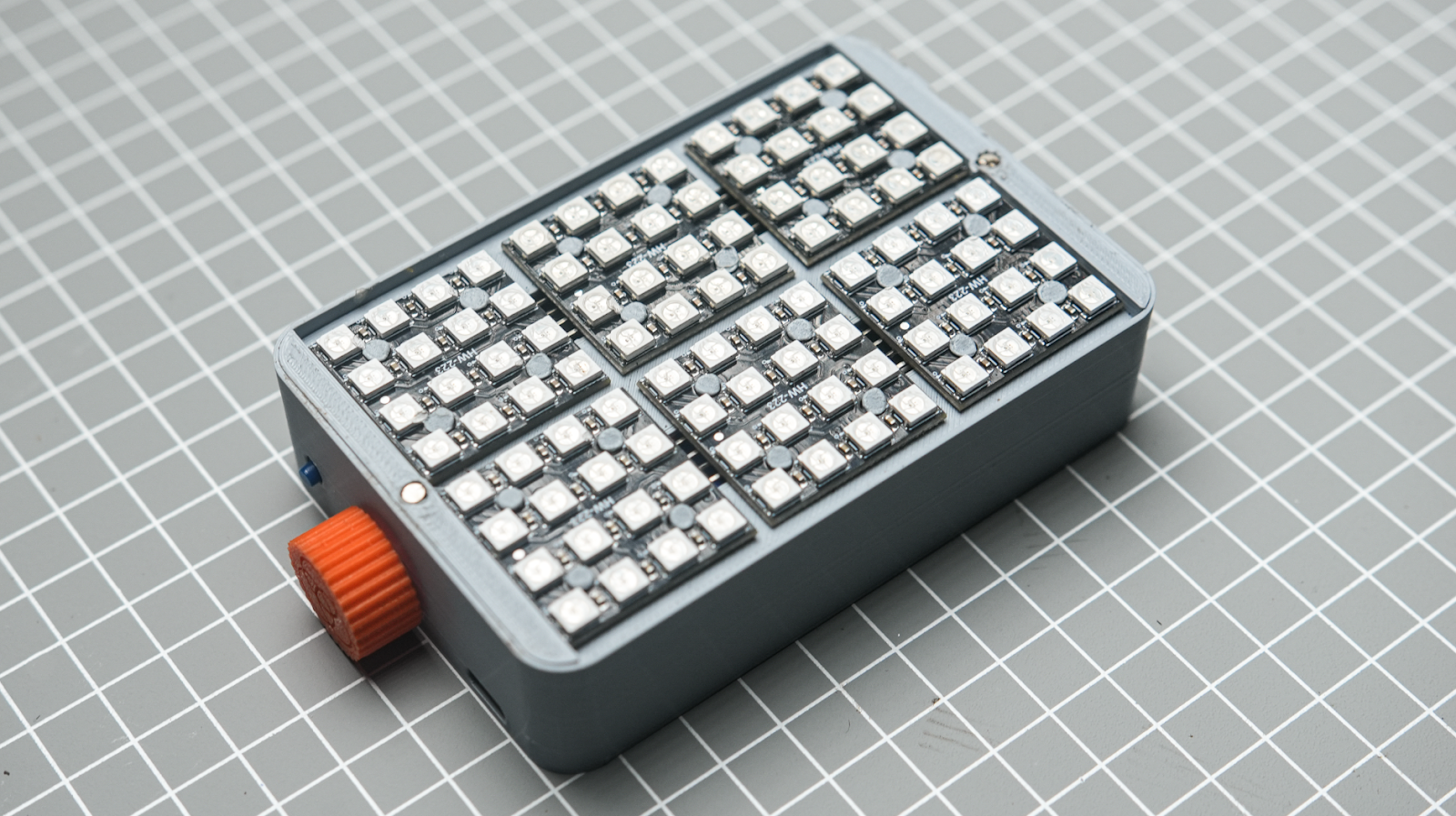
8.1
Insert the LED PCBs into the LED panel holder 3D print. While aligning the 4 holes of the LED PCB with the 3D printed tabs, make sure the "HW-223" text on the PCB is facing the right way. This will help ensure that the soldering pads on the back side of the PCB are aligned.
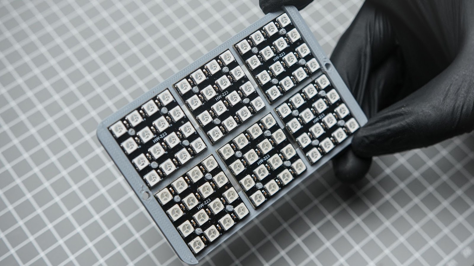
8.2
Now by using the heat staking method, we will secure the PCB into the 3d print. you can do it by melting the labs using a soldering iron. it is better to do this in a well-ventilated area workspace. also, pay attention to not damage any LED
Step 9: LED Panel Wiring and Assembly
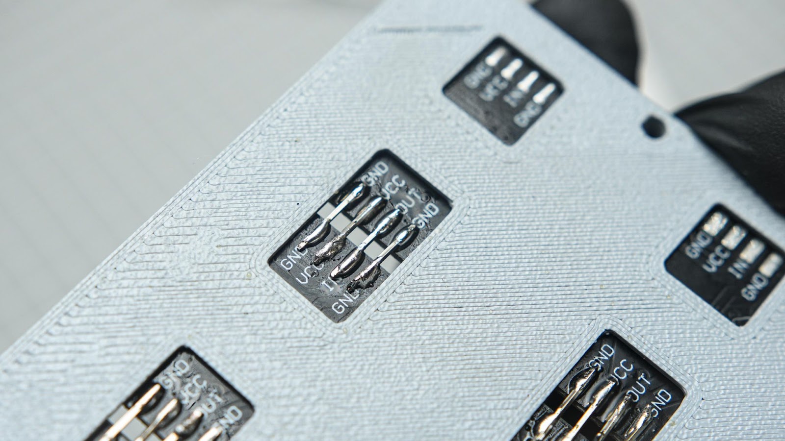
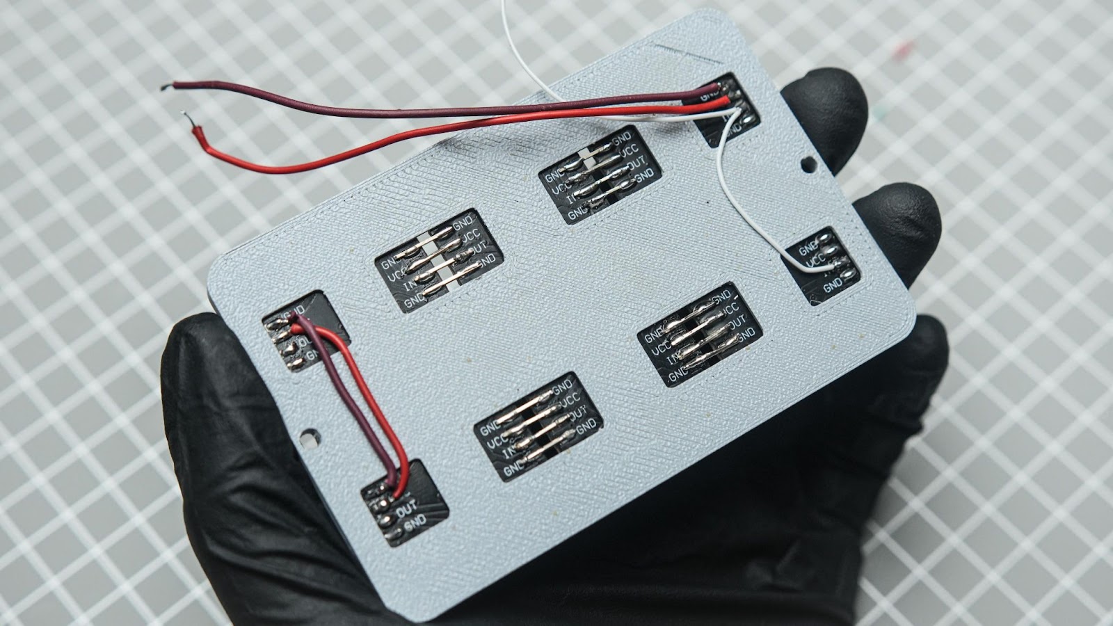
9.1
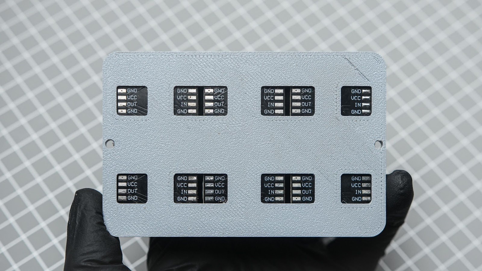
To connect the output from one LED PCB to another LED PCB input, we will use header pins. We will only need the soldering pins for this, which can be extracted using a pair of nose pliers. If you prefer, you can also use wires for the connection.
9.2
Use the pins to solder and connect all soldering pads. Use tweezers to hold the pins.
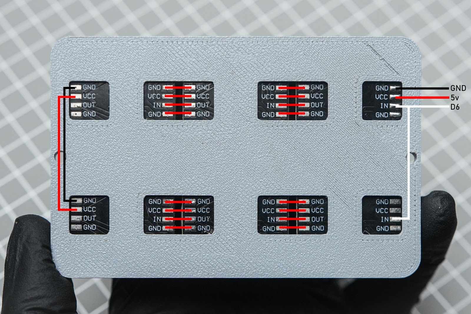
9.3
Connect the top and bottom pins using some wires. Solder external wires from GND, VCC, and IN. Follow this wiring diagram.
9.4
Connect the LED panel wires to the Xiao and BMS.

9.5
Remember to apply glue to the sides of the 3D print, then close it down.
9.6
Now, use a flat-tipped screwdriver to insert and push the 3mm magnets into the side holes.
We just completed the LED light assembly
Step 10: Assembling Accessories
Before inserting the magnets into the accessories, it is important to ensure that the magnetic poles are correct. You can determine the magnetic poles by placing the magnets on the LED panel. As you know, like poles of the magnets repel each other, so this will help you identify the correct orientation. After finding the orientation place the magnets into the diffuser holes on the side
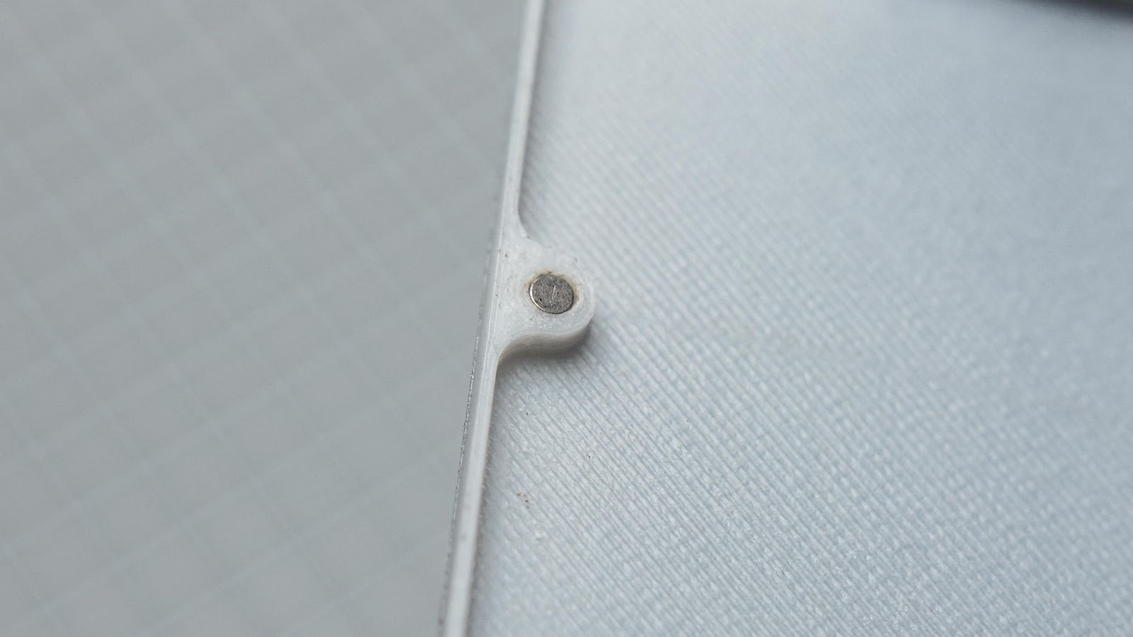
Do the same thing for the Grid attachment and insert the magnet into the 3D-printed holes
If all the magnetic poles are correct all of the accessories will fit correctly
Step 11: How to Mount the Light
We can use the 1/4-inch thread on the bottom to mount it to a light stand or any other tripod. Additionally, if you need to mount it to a camera with a hot-shoe mount, we can use a 1/4" Flash Hot Shoe Screw Adapter.
Step 12: Final Thought

When you charge this device, the light will power on by itself because of the BMS module. It's best to reduce the brightness to zero while charging this light. For this project, we used an ESP32, which might be overkill, but the size of the MCU matters. You can also install WLED to run this light wirelessly. I decided to use an encoder to make this project simple to use right away. You don't need to set up any app or anything, as it's straightforward. So, go ahead, build one and brighten up your creation with beautiful colours
handcrafted by Gokul