Story
10 POINTS VOLTMETER, HIGH RESOLUTION
Circuit presentation
The LM3914 integrated circuit is well known. Its capsule with the meaning of the pins is presented in this datasheet.
https://www.ti.com/lit/ds/symlink/lm3914.pdf
The IC is especially known for controlling the light emitting diodes (LEDs) installed in the line, hence the name bar-graph. The LM3914 integrated circuit can control 10 LEDs, of which it illuminates either one or the entire column, up to the significant level. This can be selected using pin 9 (MODE SELECT - J2). The value of the applied voltage is done in equal steps (linear display).
The diagram shown also contains an artifice (made with the LM358 operational amplifier). It generates a voltage
alternating triangular that overlaps the input voltage (from pin 5). In this way the diodes will light up
so:
- when the input voltage (applied by R1 to pin 5) is halfway between the threshold voltages of the two diodes, they will continue to be lit with the same intensity;
- the closer the measured voltage is to the threshold of an LED, the brighter it will shine, but the previous diode will still shine visibly. Thus, with a little training, it will be possible to appreciate the intermediate values. Resistor R1 limits the input current.
With the help of the RV1 semi-adjustable, the input sensitivity is adjusted to about 2V. The semi-adjustable RV2 measures the level of the triangular signal, adjusting it so that at an intermediate input voltage the two LEDs light up with the same intensity. If a diode is clearly lit, the other two LEDs on either side of the diode must be off. The adjustment will be made with the help of a voltage source.
It is useful to sort the light emitting diodes before mounting them in the circuit to have the same efficiency.
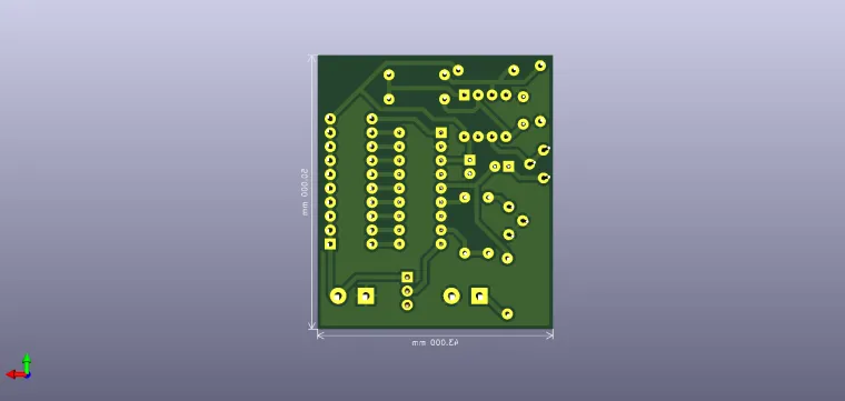
Note: I am not the original author of this circuit. The 3D model preview is just for aspect.
Enjoy it!


