I2CEncoder V2.1
Features
- I2C bus working up to 400kHz
- Possibility to customize the I2C address by soldering the 7 SMD jumpers
- It supports the standard rotary encoder and the RGB encoder
- Support gamma correction for the LEDs
- Support automatic fading
- Open-drain Interrupt output pin, so no need to continuously poll the devices
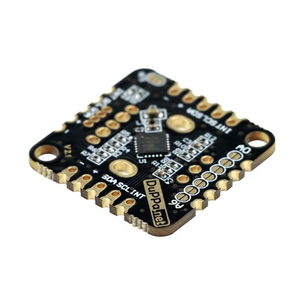
- With the castellated holes it is possible to connect several boards on the 4 sides
- 5 pin header 2.54mm pitch on the left and right side, also the JST-XH fit
- 3 General Purpose pins. (GP pins)
- 256byte of internal EEPROM divided into 2 banks of 128 byte
- Voltage range is 3.3V to 5V
- Maximum A/B signal frequency: 100Hz (Tested)
- Dimension of 25x25mm or 0.98×0.98in
- Open source firmware
Details
This new version is powered by the PIC16F18345. Respect to the MCU on the first version, it has more GPIO and the EEPROM memory. The new design of the board support both the standard encoders and the illuminated RGB encoders. Moreover, there are the castellated holes on all the 4 sides of the board, in this way will be possible to connect multiple boards by soldering them like a matrix.

The I2C Encoder V2 have also pre-soldered the pull-up resistor on the I2C bus. The can be enabled by soldering a jumper.

The I2C Encoder V2 can be used in two different scenarios:
- With a standard rotary encoder. Plus you can add an external RGB LED, or you can use the 3 GPIOs
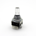
- With an illuminated RGB rotary encoder. Plus you can use 2 GPIOs.
Reading the encoder is a very easy task.
There are 4 registers:
- CVAL: Current value of the Encoder. This value changes every time the encoder rotates.
- CMAX: Maximum value that CVAL can reach
- CMIN: Minimum value that CVAL can reach
- ISTEP: How much the CVAL has to increment at each and every encoder step.
These 4 registers can be 32bit signed INT, or as float numbers IEEE 754.
LEDs
The I2C Encoder has also the possibility to control LEDs. The LEDs are controlled by an 10bit PWM.
There is also the possibility to enable a gamma correction for the LED color.
GPIOs
There are also 3 configurable GPIOs organized with the same footprint of an RGB LED. They are called GP1, GP2, and GP3. But in case you are using the RGB encoder, the configurable GPIOs are only 2: GP1 and GP2.
Possible configuration:
- PWM: In this way, you can add an RGB LED
- Analog: The pins are connected to the internal ADC of the PIC. In this way, you can add sensors or potentiometer according to your project needs
- Output: You can use the pins as standard digital output
- Input: You can use the pins as standard digital input. Plus you can configure also the interrupt on the edges

Documentation:
Projects:
Package includes:
1 I2C Encoder V2.1 board fully programmed (without encoder, connector and LED)


