EspoTek Labrador: Easy-to-Use, All-in-One USB Oscilloscopes
- Buy 2 for $26.10 each and save 10%
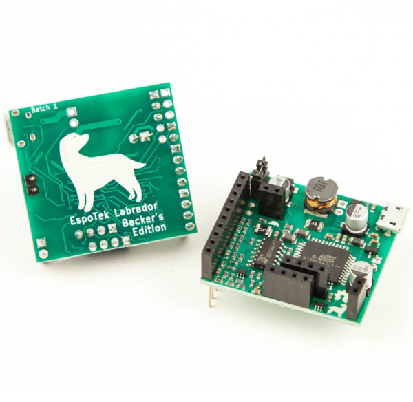
EspoTek Labrador is an all-in-one tool for electronics students, makers and hobbyists. Just plug your Labrador board into a PC (Windows/Mac/Linux), Raspberry Pi or Android device via a MicroUSB cable, load up the software and you instantly have the following engineering tools at your disposal:
- Oscilloscope (2 channel, 750ksps)
- Arbitrary Waveform Generator (2 channel, 1MSPS per channel)
- Power Supply (4.5 to 12V, 0.75W max output, with closed-loop feedback)
- Logic Analyzer (2 channel, 3MSPS per channel, with serial decoding)
- Multimeter (V/I/R/C)
Oh, and did I mention that both hardware and software are 100% open-source?

Support and Documentation:
Labrador users have access to the best support possible: a direct email link to the product developer. If you have any issues or suggestions, email admin@espotek.com and I’ll do what I can to help; be it getting the software running on an unsupported OS, adding in a feature you’d like or just getting your board up and running.
In addition to this, community support and discussion is available at the GitHub Issues Page.
Full documentation (including pinout and a tutorial for beginners) for the hardware and software is available at the GitHub Wiki Page.
Full specs:
| Oscilloscope | Sample Rate | 750ksps (shared) |
| Bits per Sample | 8, 12¹ | |
| Bandwidth | ~100kHz² | |
| Input Voltage Range | -20V to +20V | |
| Input Impedance | 1 MΩ | |
| No. of Channels | 2 | |
| Coupling | AC/DC | |
| Arbitrary Waveform Generator | Waveform types | Sin, Square, Triangle, Sawtooth, Arbitrary |
| Sample Rate | 1Msps | |
| Sample Depth | 512 samples per channel | |
| Output voltage range | 0.15V to 9.5V | |
| Bits per Sample | 8 | |
| Max. Current | 10mA³ | |
| Output Resistance | 50Ω | |
| No. of Channels | 2 | |
| Variable Power Supply | Voltage Range | 4.5V to 12V |
| Max. Power | 0.75W | |
| No. of Outputs | 1 | |
| Source Impedance | Negligible⁴ | |
| Ripple Voltage | +-300mV%@10V 10mA, +-700mV%@10V 100mA | |
| Logic Analyzer | Sample Rate | 3Msps per channel |
| Supported voltage | 3.3V, 5V, 12V | |
| No. of Channels | 2 | |
| Digital Output | Voltage | 3.3V |
| Source Impedance | 50Ω | |
| Multimeter⁵ | Input Impedance | 1MΩ |
| Measured Parameters | V, I, R, C | |
| Voltage Range | -20V to +20V | |
| Current Range | 100uA to 10A | |
| Resistance Range | 1 ohm to 100k | |
| Capacitance Range | 10nf to 1mf | |
| Supported Platforms | Windows | Windows 7, 8, 8.1 or 10. 32 and 64-bit supported. |
| MacOS | 10.10 (Yosemite) or later | |
| Linux | Ubuntu 14.04 or later (or similar). 32 and 64-bit supported. | |
| Android | Version 4.1 or later |
¹ – 12-bit sampling is available at 375ksps, single-channel only.
² – This figure is an approximate “maximum detectable frequency” dictated by the sample rate.
³ – This figure is for source current. Current is sunk partially into the opamp driving the signal gen and partially into a 1k resistor. Thus, maximum sink current can be calculated by dividing the output voltage by 1k and adding 50µA. This configuration was chosen so that capacitive loads could be driven without significant nonlinearities. In simpler terms, this means that if you’re trying to drive current into the waveform generator through use of an external current source, then the maximum current that the waveform generator can handle is reduced. (This is not something that would be an issue for most people.)
⁴ – The Power Supply is controlled by a closed-loop feedback loop that ensures the DC voltage across output remains constant. Thus, it has nonlinear elements, but can still be approximated by a Thévenin circuit with Vth = Vo and Rth = 0.
⁵ – Multimeter ranges vary with reference resistor used.
Product Photos used with permission under a Creative Commons Licence from Crowd Supply Inc


