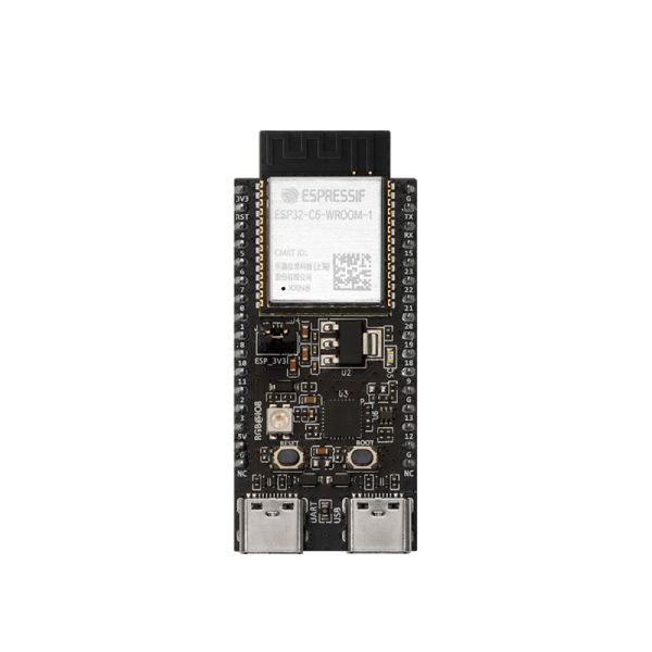
ESP32-C6-DevKitC-1-N8 module
Description
ESP32-C6-DevKitC-1 is an entry-level development board based on ESP32-C6-WROOM-1, a general-purpose module with a 8 MB SPI flash. This board integrates complete Wi-Fi, Bluetooth-compatible LE, Zigbee, and Thread functions.
Most of the I/O pins are broken out to the pin headers on both sides for easy interfacing. Users can either connect peripherals with jumper wires or mount ESP32-C6-DevKitC-1 on a breadboard.
[Noted] The current product has not been calibrated for ADC, and it is not recommended to use the ADC function; the order chips for subsequent shipments will complete ADC calibration before leaving the factory.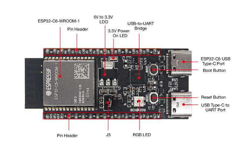
|
Key Component |
Description |
|
ESP32-C6-WROOM-1 |
ESP32-C6-WROOM-1 is a general-purpose module supporting Wi-Fi 6, Bluetooth-compatible 5, and IEEE 802.15.4 (Zigbee 3.0 and Thread). This module is built around the ESP32-C6 chip and comes with a PCB antenna and an 8 MB SPI flash. |
|
Pin Header |
All available GPIO pins (except for the SPI bus for flash) are broken out to the pin headers on the board. |
|
5 V to 3.3 V LDO |
Power regulator that converts a 5 V supply into a 3.3 V output. |
|
3.3 V Power On LED |
Turns on when the USB power is connected to the board. |
|
USB-to-UART Bridge |
Single USB-to-UART bridge chip provides transfer rates up to 3 Mbps. |
|
ESP32-C6 USB Type-C Port |
The USB Type-C port on the ESP32-C6 chip is compliant with USB 2.0 full speed. It is capable of up to 12 Mbps transfer speed (Note that this port does not support the faster 480 Mbps high-speed transfer mode). |
|
Boot Button |
Download button. Holding down the Boot and then pressing Reset initiates Firmware Download mode for downloading firmware through the serial port. |
|
Reset Button |
Press this button to restart the system. |
|
USB Type-C to UART Port |
Used for power supply to the board, as well as the communication with the ESP32-C6 chip via the onboard USB-to-UART bridge. |
|
RGB LED |
Addressable RGB LED, driven by GPIO8. |
|
J5 |
Used for current measurement. |
Block Diagram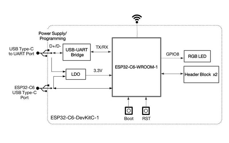
Pin Layout(Top View)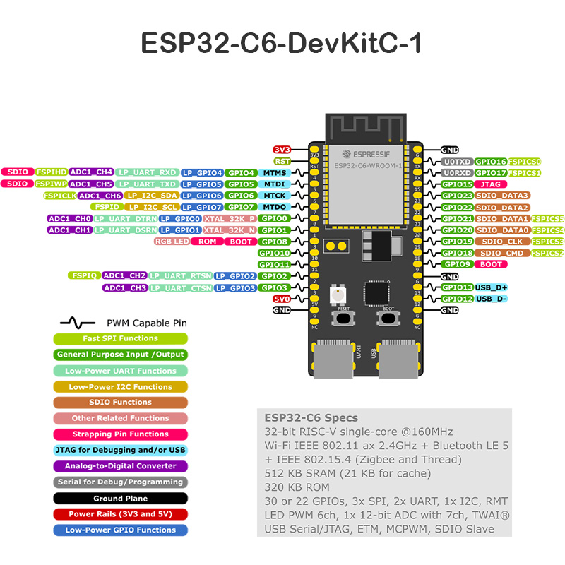
J1 Pin Description
|
No. |
Name |
Type 1 |
Function |
|
1 |
3V3 |
P |
3.3 V Power Supply |
|
2 |
RST |
I |
High: enables the chip; Low: disables the chip. |
|
3 |
4 |
I/O/T |
MTMS3, GPIO4, LP_GPIO4, LP_UART_RXD, ADC1_CH4, FSPIHD |
|
4 |
5 |
I/O/T |
MTDI 3, GPIO5, LP_GPIO5, LP_UART_TXD, ADC1_CH5, FSPIWP |
|
5 |
6 |
I/O/T |
MTCK, GPIO6, LP_GPIO6, LP_I2C_SDA, ADC1_CH6, FSPICLK |
|
6 |
7 |
I/O/T |
MTDO, GPIO7, LP_GPIO7, LP_I2C_SCL, FSPID |
|
7 |
0 |
I/O/T |
GPIO0, XTAL_32K_P, LP_GPIO0, LP_UART_DTRN, ADC1_CH0 |
|
8 |
1 |
I/O/T |
GPIO1, XTAL_32K_N, LP_GPIO1, LP_UART_DSRN, ADC1_CH1 |
|
9 |
8 |
I/O/T |
|
|
10 |
10 |
I/O/T |
GPIO10 |
|
11 |
11 |
I/O/T |
GPIO11 |
|
12 |
2 |
I/O/T |
GPIO2, LP_GPIO2, LP_UART_RTSN, ADC1_CH2, FSPIQ |
|
13 |
3 |
I/O/T |
GPIO3, LP_GPIO3, LP_UART_CTSN, ADC1_CH3 |
|
14 |
5V |
P |
5 V power supply |
|
15 |
G |
G |
Ground |
|
16 |
NC |
– |
No connection |
J3 Pin Description
|
No. |
Name |
Type |
Function |
|
1 |
G |
G |
Ground |
|
2 |
TX |
I/O/T |
U0TXD, GPIO16, FSPICS0 |
|
3 |
RX |
I/O/T |
U0RXD, GPIO17, FSPICS1 |
|
4 |
15 |
I/O/T |
GPIO15 3 |
|
5 |
23 |
I/O/T |
GPIO23, SDIO_DATA3 |
|
6 |
22 |
I/O/T |
GPIO22, SDIO_DATA2 |
|
7 |
21 |
I/O/T |
GPIO21, SDIO_DATA1, FSPICS5 |
|
8 |
20 |
I/O/T |
GPIO20, SDIO_DATA0, FSPICS4 |
|
9 |
19 |
I/O/T |
GPIO19, SDIO_CLK, FSPICS3 |
|
10 |
18 |
I/O/T |
GPIO18, SDIO_CMD, FSPICS2 |
|
11 |
9 |
I/O/T |
GPIO9 3 |
|
12 |
G |
G |
Ground |
|
13 |
13 |
I/O/T |
GPIO13, USB_D+ |
|
14 |
12 |
I/O/T |
GPIO12, USB_D- |
|
15 |
G |
G |
Ground |
|
16 |
NC |
– |
No connection |
1. P: Power supply; I: Input; O: Output; T: High impedance.
2. Used to drive the RGB LED.
3. (1,2,3,4,5)
MTMS, MTDI, GPIO8, GPIO9, and GPIO15 are strapping pins of the ESP32-C6 chip. These pins are used to control several chip functions depending on binary voltage values applied to the pins during chip power-up or system reset.
Feature
- Equipped with RISC-V 32-bit single-core processor, the operating frequency is up to 160 MHz with 320 KB ROM,512 KB SRAM,16 KB Low-power (LP) SRAM
- Support IEEE 802.11ax protocol, IEEE 802.11 b/g/n-compliant
- Support Bluetooth-compatible BLE 5
Specification
- Model: ESP32-C6-Devkit-C-N8 Module
- Chip: ESP32-C6 chip, RISC-V 32-bit single-core processor, supports clock frequency up to 160 MHz
- Works in 2.4 GHz frequency band, 1T1R
- Supports Bluetooth-compatible Low Energy 5.0
- Support IEEE 802.11ax protocol,
- Compatible with IEEE 802.11b/g/n protocols, supporting 20 MHz and 40 MHz bandwidth-data rates up to 150 Mbps
- Compatible with IEEE 802.15.4-2015 protocol, working in 2.4 GHz frequency band, supporting OQPSK PHY/Thread 1.3/Zigbee 3.0
- Antenna form: onboard PCB antenna
- Operating temperature:-40℃~85℃
- SPI Flash: 8MB
- Size: 51.8*25.4mm
- Weight: 10.1g
Package List
- 1x ESP32-C6-WROOM-1-N4

