Currency
Toggle Nav

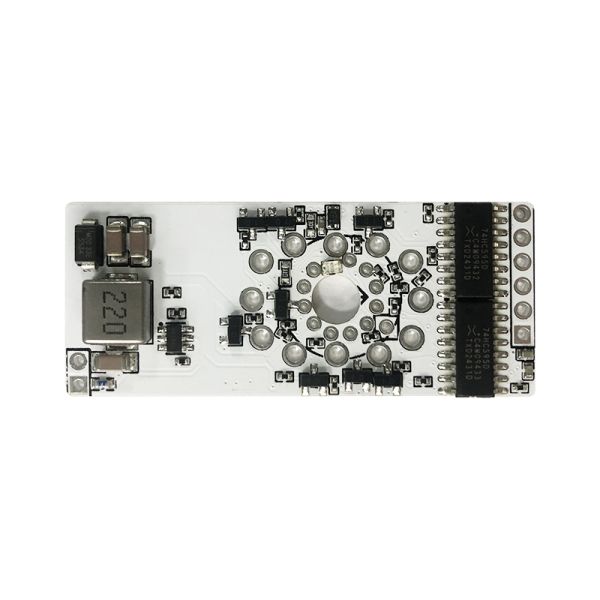


EasyVFD: Drive your retro VFD Tubes with ease
$14.00
Availability:
In stock
SKU
CQE0005VFD
Weight
50g
- Buy 10 for $12.00 each and save 14%
Related Products:

×
 Add to cart successfully!


Customers Who View This Item Also Bought
This is a retro display driver designed to control IV-11, IV-6, and IV-22 VFD tubes.
Frequently Bought Together


What is it?
This is a retro display driver designed to control IV-11, IV-6, and IV-22 VFD tubes.
What makes it special?
- On-board 5V to 28V step-up converter
- Works with 3.3V logic
- Allows daisy-chaining of multiple units
- VFD displays require lower voltage than Nixie tubes, making them much safer
- Silent operation with no noise
- EasyNixie-compatible pinout
- RGB lighting support
- Arduino Library available
How do I connect it?
Connect it the same way you would connect a shift register.
- STCP->GPIO
- SHCP->GPIO
- DSIN->GPIO
- DSOUT->DSIN of the next EasyPDLC in daisy chain or 'not connected'
- OUT_EN->GPIO
- VLOGIC->3.3V or 5V depending you your MCU logic votlage
- VPOWER->5V
- GND->GND
When you connect IV-22 VFDs refer to IV-22 datasheet, there is only two ways you can connect it, so it's not too hard. IV-22 segment names are written on the PCB.
While determining the orientation of IV-11, you can check where VFD pins 1, 2 and 11 goes. Pin 1 goes to 1V5 hole, pin 2 goes to GRID hole, pin 11 goes to GND. Please disregard the segment names written on the PCB; they are slightly mixed up.
For IV-6, note that the gap between the VFD pins(pin 12 is cut) on the VFD itself corresponds to the gap between the pads on the PCB. Please disregard the segment names written on the PCB; they are slightly mixed up.
Write Your Own Review
Bestselling Products You May Like


New Products You May Want