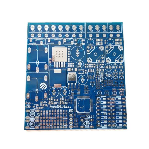
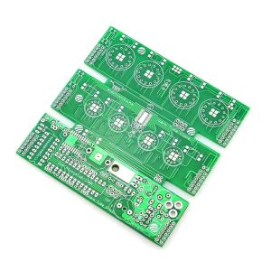
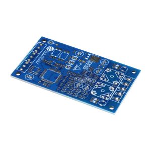
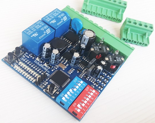
Blank PCB for Dual Channel Inductive Loop Vehicle Detector (A)
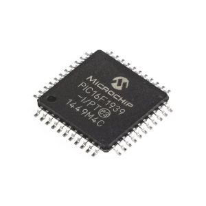
Inductive Loop Detector works by detecting an inductance change in wire loop (coil) that is buried in road. It does that by measuring the frequency of the internal oscillator which powers the mentioned coil. When a metallic object moves over the coil it changes its inductance and that in turn changes the oscillator frequency which is measured by the microcontroller. We can provide pre-programmed PIC chip to meet your requirement on this project.
It is used for vehicle access control at door and barrier controls, for monitoring the occupancy and for vehicle counting in parking garages, for traffic light installations and traffic controllers, for direction and speed detection of vehicle traffic, in car-wash plants, etc. This device can also work as an independent speed trap and can be easily interfaced to Arduino.
Specifications
· Number of operating modes: 4
· Tuning: Automatic
· Detection type: Presence/Pulse
· Presence time: Adjustable in 3 steps
· Pulse duration: 250 ms / 500 ms
· Signal filtering: Adjustable in 2 steps (NORMAL, HIGH)
· Loop inductance: 20 uH – 1000 uH
· Frequency range: 20 kHz – 145 kHz
· Frequency selection: 2 combinations (LOW, HIGH)
· Sensitivity: Maximum 0.0025% Δf/f, adjustable in 8 steps
· Detection speed: 10 ms by default, adjustable
· Start-up time: ~ 1 second per channel (or longer if frequency is not stable)
· Temperature range: -35°C – 120°C
· Sensor protection: Galvanic isolation + gas discharge tube for lightning protection
PCB details
· PCB thickness: 1.6mm
· Copper weight: 1oz 35um
· PCB color: blue
· Surface finish: HASL
Modes of operation
· Single Channel (only A)
· Dual Channel Independent A & B
· Dual Channel Directional Logic A + B
· Speed Trap A + B
Package list
· Dual Channel Inductive Loop Vehicle Detector - v1.2 PCB Board x 1
Wiki & External links
More details

 Bosnia and Herzegovina
