Currency
Toggle Nav

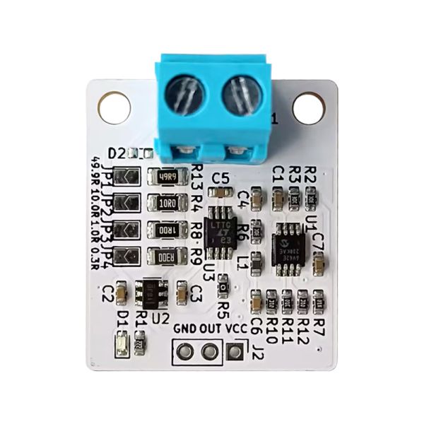


CT Sensor Amp
$35.00
Availability:
In stock
SKU
CQR240402S
Weight
41g
- Buy 5 for $32.00 each and save 9%
- Buy 10 for $30.00 each and save 14%
Related Products:


×
 Add to cart successfully!


Customers Who View This Item Also Bought
This board is a board that amplifies the output of a clamp-type CT sensor and converts it into an RMS value (effective value)
Frequently Bought Together


Feature
- This board is a board that amplifies the output of a clamp-type CT sensor and converts it into an RMS value (effective value).
- You can obtain the RMS value (effective value) according to the AC current as an analog value (DC).
- Equipped with shunt resistance and RMS value calculation IC, it is possible to obtain the effective value of AC current as an analog value.
- Since the effective value can be obtained as an analog value, there is no need for high sampling AD conversion or RMS calculation on the microcontroller side.
- Uses CT sensor input amplifier INA181A1 amplifier, RMS conversion LTC1966, low offset output amplifier MCP6V62.
- Shunt resistance can be selected from 4 types: 49.9Ω, 10Ω, 1Ω, 0.3Ω.
- Although it varies depending on the shunt resistance and CT sensor, it can measure from a minimum of 0.1A to a maximum of 300A (at 3.3V power supply)
- Board size 25mm x30mm, fixing hole M3x2 width 20mm
Conversion formula
20x gain with INA181A1 and 3x output stage amplifier gain for a total amplification factor of 60x
VOUT= (I x Gain x R)/CT
I = (VOUT x CT)/(Gain x R)
VOUT: Analog output voltage (V), I: CT sensor target current (A), Gain: 60 times (fixed), R: Shunt resistance (Ω), CT: Winding ratio
Example VOUT=(IxGainxR)/(CT ratio)=(Ix60x49.9)/3000
Important Points
- CT sensor is not included.
- Please use a CT sensor with a winding ratio of around 1:2000 to 3000.
- When using, be sure to jumper one of the shunt resistors.
- Due to the characteristics of CT sensors, if the secondary side is opened with a live wire, a voltage of several kV will be generated, which may damage the CT or cause electric shock.
- To prevent CT damage and electric shock, we recommend using a CT sensor with a built-in output protection element.
- The power supply supports 3.3V and 5V, but a 5V power supply has a wider range and can measure more current.
- Outputs higher than the power supply voltage will cause the amplifier to saturate and will not be output correctly.
- Due to the input impedance and offset voltage of AD conversion, an output voltage of several tens of mV occurs even at a current of 0 A.
- Not suitable for small current measurements below the minimum current in each shunt resistor.
- Intended for use in measuring 50Hz/60Hz commercial power supply current with a CT sensor.
- True RMS value calculation is obtained using an RMS calculation IC, but if there is large distortion or noise, accurate measurements may not be possible.
- A low-pass filter on the circuit cuts off high frequencies, so current changes over several hundred Hz cannot be measured.
Shunt resistance and measurement current range guide
These are the minimum and maximum current guidelines for each shunt resistance when using a 1:3000 CT sensor.
The maximum current is set based on the voltage that is a guideline for amplifier saturation.
The minimum current generates an offset voltage of several tens of mV, so it is set as a guideline so that the effect can be ignored.
| Shunt Reg | Min Current(3.3V) | Max Current(3.3V) | Min Current(5V) | Max Current(5V) |
| 49.9 ohm | 0.1A | 3A | 0.1A | 5A |
| 10.0 ohm | 0.5A | 15A | 0.5A | 23A |
| 1.0 ohm | 5A | 150A | 5A | 230A |
| 0.3 ohm | 10A | 340A | 10A | 500A |
Write Your Own Review
Bestselling Products You May Like


New Products You May Want