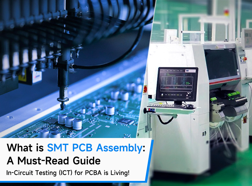
What is SMT PCB Assembly: A Must-Read Guide

Must-Read Guide for SMT PCB Assembly
Various techniques, including SMT, through-hole, manual, and combined technologies, are used to create printed circuit boards or PCBs. You have come to the right place if you are keen to learn about the SMT PCB assembly procedure! This comprehensive page will teach you the definition of SMT assembly and its benefits and drawbacks. A thorough description of the complete SMT assembly production process will also be provided to you. Why wait, then? Learn all about SMT PCB assembly by reading on!
What Does Surface Mount Technology PCB Mean?
The process of mounting electrical components onto a printed circuit board (PCB) surface is known as Surface Mount Technology (SMT). SMT saves space and enables higher-density circuit designs by allowing smaller components to be mounted on both sides of the PCB, in contrast to traditional through-hole technology, which involves inserting components into holes and soldering them to the board's underside.
SMT PCB Assembly Process Steps
The surface mount PCB assembly procedure is simple and includes several highly efficient automated phases.
1. Stencil Printing
Using a squeegee, stencil printing first applies solder paste to the PCB, guaranteeing uniform distribution and regulating variables like speed and viscosity to avoid flaws.
- Stencil Design: Based on the PCB design and SMT component specifications, you must choose the stencil thickness, aperture size, and shape of the design.
- Solder Paste Inspection: An SPI machine is used to examine solder paste deposits after printing. It automatically confirms the deposits' existence, volume, and alignment on each pad, assisting in the early detection of printing flaws so that they may be fixed on time.
2. Placement of Components
Pick-and-place or Chip Shooter machines with a vision system for accurate placement are then used to attach the components to the printed solder paste.
- Pick-and-Place Machine Programming: Accurate component information, including type, size, and placement coordinates, must be programmed into pick-and-place machines using the PCB design files and entered into the control software.
- Component Feeders: Depending on the size and number of the SMT components, several feeders—such as tape-and-reel, tube, or tray—are used to convey them to the pick-and-place machine.
3. Reflow Soldering
Subsequently, reflow soldering uses an inert atmosphere to prevent oxidation while melting the solder paste in an oven with a certain temperature profile to produce robust connections.
- Reflow Temperature Profile: Successful solder junctions depend on the reflow temperature profile, which includes steps like preheating, soak, reflow, and cooling, each of which has exact temperature and time requirements.
- Nitrogen Atmosphere: Some reflow ovens utilize a nitrogen atmosphere to minimize oxidation and enhance solder joint quality by displacing oxygen and preventing oxide formation on the solder surface during reflow.
4. Quality Inspection
Finally, to ensure that your built PCBs meet high requirements, quality is tested using X-ray inspection and Automated Optical Inspection (AOI) to identify any flaws. This simplified & easy procedure allows you to produce surface-mount PCBs with reliability and efficiency.
- Visual Inspection
- X-Ray Inspection
- Functional Testing
Pros & Cons of SMT PCB Assembly
|
Pros |
Cons |
|
|
|
Applications of SMT PCB Assembly
The electronics industry has seen a revolution because of SMT assembly, which has made it possible to create dependable, high-performing, and small devices for a variety of uses. The following are some important sectors and goods that SMT PCB assembly helps:
- Consumer electronics: SMT assembly allows devices like laptops, tablets, smartphones, and wearable technology to be small and have a high component density.
- Telecommunications: SMT satisfies the need for bigger bandwidths and faster transmission rates by supporting high-frequency components in networking hardware, routers, and modems.
- Automotive Electronics: SMT offers dependable and small modules for ADAS and ECUs in cars, increasing productivity and security.
- Aircraft and Defense: SMT is crucial for small, robust navigation and avionics systems that satisfy demanding aircraft specifications.
- Medical Devices: SMT assembly guarantees small, dependable electronic parts that adhere to stringent safety regulations in diagnostic and therapeutic devices.
- Industrial Automation: SMT supports robust and effective automation technology systems such as PLCs, HMIs, and robotics controllers.
SMT vs THT
For miniaturized electronics, SMT (Surface Mount Technology) allows for smaller, more compact designs with a higher component density by mounting components directly onto the PCB surface. Although the joints are often weaker than THT, its automated assembly makes it quicker and more affordable for high-volume manufacture.
By putting components via holes in the PCB, THT (via-hole Technology) creates stronger mechanical bonding appropriate for high-stress or high-vibration applications. THT is useful for applications that need strong, dependable connections, like industrial, automotive, and aerospace equipment, even if it is bigger and less effective than SMT.
What's more?
The intricate SMT assembly process requires meticulous preparation, execution, and quality assurance. You can guarantee the success of your SMT PCB assembly by understanding the principles of SMT components, PCB design, solder paste printing, component placement, reflow soldering, inspection, and testing. Whether you work with an outside supplier or manage SMT assembly internally, these factors will help you produce reliable, high-quality PCB assembly.
________________________________________________________________
Exciting News! Elecrow now offers Free In-Circuit Testing (ICT)! This service efficiently checks the electrical connections and functionality of your PCBA. Using a special test probe, we inject test signals into the circuit to ensure that all components are connected and performing as they should. It's perfect for high-value projects that involve multiple components and require stable, ongoing orders.
While the testing labor is complimentary, please note that the fixture fee ranges from $300 to $1,000 per project. The cost increases with the number of circuits on the board, but the good news is that the fixture can be reused for future orders. This makes ICT an ideal choice for projects with continuous re-orders. Know more about it here.
