Unraveling the Basics of PCB Vias: Everything You Need to Know

Prologue
In the realm of printed circuit boards, there is a tiny yet powerful component that holds the key to seamless connectivity and efficient signal flow - the PCB vias. These inconspicuous holes serve as the critical link between different layers, ensuring the smooth transmission of electrical signals.
Whether you're a curious beginner or a seasoned professional, this blog is your go-to resource for understanding the essentials of these vital connectors– PCB vias.
What is a PCB Via?
A PCB via is a tiny hole that connects two or more adjacent layers, enabling signals and power to flow between them. These are crucial for establishing inter-layer connections in multilayer PCBs since circuits between layers are independent. Vias are classified into three types based on their function: blind via, buried via, and through-hole via.
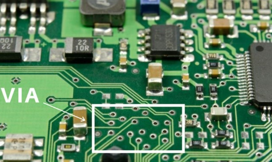
Types of PCB Vias
There are three types of vias in PCB design.
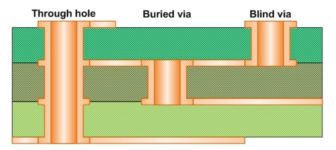
1. Blind vias(From outer layer to inner layer)
Blind vias connect from one side of the outer layer to at least one inner layer but do not go through the entire board. They are useful for freeing up space and are commonly used in BGA assembly and HDI PCBs.
2. Buried vias(From inner layer to inner layer)
Buried vias connect at least two inner layers and are not visible on the outer layer. They are designed to reduce signal interference and are ideal for HDI PCBs.
3. Through-hole vias (From outer layer to outer layer)
Through-hole vias, the most common type of vias, connect the inner and outer layers and go through the entire board. They are used for internal interconnection or as mounting holes for components.
Other Types of PCB Vias
Mircrovias
Microvias are vias that are under 150 microns in size and are commonly used in high-density interconnect (HDI) PCBs due to their small hole size. They connect layers with copper plating and take up less space on the circuit board. Copper plating micro vias is easy because of their cone shape, and they can pass through two adjacent layers but cannot go further. If multiple layers require vias, multiple micro vias must be stacked accordingly.
Via-in-Pad
Via-in-Pad is a popular via type that involves placing vias on ball grid array (BGA) pads. This design reduces the amount of space needed for vias, enabling manufacturers to create smaller PCBs. Buried and blind vias have their benefits, as do other types of vias. The type of vias used depends on the technology of the printed circuit board.
Benefits of PCB Vias
There are advantages to both buried vias and blind vias, as well as other types of vias. The appropriate type of vias to use will depend on the technology of the printed circuit board.
Signal routing
For denser printed circuit boards, blind or buried vias are used to enhance signal routing. Micro vias are also ideal for much denser printed circuit boards.
Power routing
The use of vias is widespread for the construction of ground and power nets. These vias can carry more current, while also being limited to larger through-hole vias.
Trace density
Vias enhance trace density in multiple layers of boards since routes can be run underneath and over each other in multiple directions. Vias allow traces to interconnect, so routes serve as vertical connections.
Signal transmissions
If you don't want to integrate Vias, PCB components will need to be routed on a single plane if you don't want to use blind Vias to transmit signals between layers. Blind vias, for instance, can effectively facilitate signal transmission between layers in a board.
PCB Via Covering Process
There are three main methods for covering vias in PCB design: tenting vias, not covering vias, and plugging vias with some solder mask.
1. Tenting vias
Tenting vias involves covering the annular ring of the via with the solder mask for insulation. It's important to make sure that the annular ring is completely covered with a thick enough solder mask to prevent accidental short circuits or contact with the circuit.
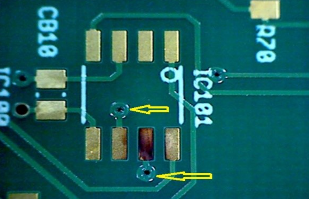
2. Vias not covered
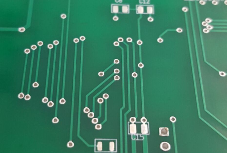
If you choose not to cover vias in your design, both the via hole and annular ring will be left uncovered. These types of vias are usually used for debugging measurement signals. Leaving vias uncovered also has the advantage of increasing the heat dissipation area, which can be helpful for heat dissipation. However, this method can easily cause a short circuit.
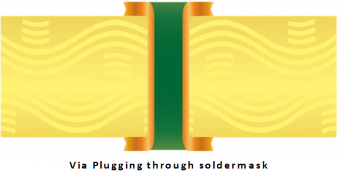
3. Plugged vias with solder mask
When it comes to wave soldering, it's important to prevent solder balls from causing short circuits and avoid any leftover flux residue in the via hole. This is where solder mask plugging comes in handy. If your board has a BGA or IC assembly, it's recommended to opt for mask-plugged vias.
Considerations for Creating PCB Vias
When designing a PCB, it is important to consider the following tips for creating good PCB vias:
1. Signal integrity: Poorly created vias can cause signal integrity problems, which can lead to interference. It is important to detect and solve these issues, such as back drilling the via to remove unnecessary metal.
2. Aspect ratio: The acceptable drill size for vias is determined by the board thickness, and there is a limit to how far a mechanical drill can penetrate. An aspect ratio of 10:1 is recommended by PCB manufacturers, but micro vias with an aspect ratio of 1:1 can be used for smaller holes.
3. Routing density: When routing dense areas of the board, avoid using vias to block up the ground plane return paths, especially under parts such as pin-count BGAs where many vias are in a small area. Routing density can be enhanced by outer layers and hole depth.
4. Annular ring: The size of the via pad is important, and a sufficient annular ring will keep the via in check and prevent drill breakout. It is important to ensure a large annular ring remains after drilling the via.
Design Tips for PCB Vias
If you're looking to design PCBs with vias, here are some tips to keep in mind:
- Opt for smaller vias, especially in HDI boards, as this can help reduce stray inductance and capacitance.
- For blind or buried vias, make sure to use controlled depth.
- If a via is within a thermal pad, be sure to fill it in unless it's located within a thermal pad itself.
- For high-speed vias, ensure a minimum aspect ratio to prevent signal reflections. This will improve signal integrity and electrical performance.
- For some pad arrangements on a BGA, you can use blind or through-hole vias.
- Staggered vias are preferable to stacked vias, as the latter requires filling and planarizing.
- Thermal vias can be used under QFNs to allow solder flow to conductive planes, creating secure solder joints that prevent the package from floating during PCB assembly.
- Make sure the copper foils and component leads are in the right condition as well as the hole diameter and fine-pitch of the BGA components for via-in-pad.
- Be sure to check the outer layer, as this plays a crucial role in creating good vias.
- Lastly, inspect the blind vias for any irregularities.
- To minimize PCB via resistance or inductance when routing a trace across the board, it's important to keep in mind that all PCB vias possess both of these characteristics. For this reason, employing multiple vias is a wise choice.
Final Words
In this comprehensive guide, we have unlocked the vital knowledge of PCB vias, equipping you with the knowledge you need to understand all the basics about PCB vias effectively. By understanding the fundamentals of PCB vias, you now have the key to unlocking a world of possibilities in your PCB layout and design.
However, sometimes conducting the PCB design yourself can be energy-consuming and challenging, that's where Elecrow comes in. As a trusted name in the industry, Elecrow offers superb PCBA (Printed Circuit Board Assembly) services that cater to a wide range of requirements and specifications.
When you choose Elecrow for your PCBA needs, you gain access to a host of benefits. Their streamlined processes, rigorous quality control measures, and commitment to customer satisfaction ensure that your PCB assembly is performed flawlessly. With their extensive experience and industry knowledge, Elecrow can guide you through the assembly process, providing valuable insight and suggestions to optimize your design for manufacturing. In addition, Elecrow offers competitive pricing and flexible options so you can find a PCBA solution that fits your budget and schedule.
And if you are interested in making money from your DIY electronics ideas, Elecrow can even help you mass-produce your electronics ideas for profit. Join our Partner Seller Program and reap the rewards!
