Explore 3 Innovative Open-Source PCB Projects on Elecrow Project Community
Explore 3 Innovative PCB Projects on Elecrow Project Community: PAA3905 Breakout Board, STM32L432 Development Board, Walkie Talkie
Explore innovative PCB projects on Elecrow's Project Community, featuring the PAA3905 Breakout Board for precise navigation in low light, the ultra-efficient Ladybug STM32L432 Development Board for wearables, and a budget-friendly walkie-talkie for reliable communication. Discover how these projects solve real-world challenges with creative ideas and innovative technology.
 Case Study 1: Ladybug STM32L432 Development Board
Overview
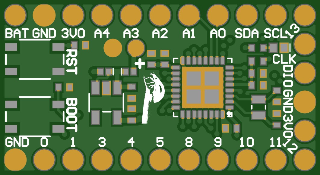
Imagine that you have a tiny, super-smart computer that is smaller than a matchbox and excels at saving battery life. The Ladybug STM32L432 Development Board functions similarly to this. It’s just like a little brain that can be commanded to control cool gadgets or robots, and it can work for a long time on a small battery, making it perfect for wearable and tiny gadgets. Its multiple functions involve motor control, light measurement, and information sharing with your computer. It is really easy to use and doesn’t need any fancy tools or complex setups. So, the Ladybug board is a clever and easy method to make something exciting and functional.
Challenge
Compact size and excessive power consumption are problems for many battery-operated gadgets. Conventional approaches frequently need large, power-hungry components that can rapidly degrade batteries and complicate designs. In order to solve these problems, the Ladybug STM32L432 Development Board provides a small, low-power solution that is simple to integrate and program. Its compact size makes it excellent for wearables and small electronics, and its ultra-low energy consumption assures a long battery life. It increases the usefulness and efficiency of tiny, smart devices by streamlining the design and lowering energy requirements.
What We Did
In order to solve challenges in creating small, low-power devices, Kris Winer, developed the Ladybug STM32L432 Development Board. His work involved designing a compact and energy-efficient board using the STM32L432 microcontroller. By adding features like ultra-low power consumption and simple USB programming, Kris created a board that is ideal for wearable and space-constrained applications. The project includes an open-source design that simplifies integration and programming, making it easier for users to build and deploy small, smart devices with extended battery life and minimal setup.
What we achieved
The project was completed successfully, resulting in a compact and highly efficient development board using the STM32L432 microcontroller. The Ladybug STM32L432 Development Board achieves extended battery life and simplified programming, making it an excellent choice for small, low-power applications. Its ultra-low power consumption and small size make it ideal for wearable tech and devices where space and energy are limited. The project has provided a practical, cost-effective solution for creating smart devices with easy integration and extended functionality.
Conclusion
In summary, the Ladybug STM32L432 Development Board project has effectively produced a tiny, energy-efficient solution that solves important issues with battery-operated, small devices. A flexible board that is perfect for wearable and space-constrained applications has been built by the project by utilizing the low power consumption of the STM32L432 microcontroller and including user-friendly features. This novel method not only increases battery life but also streamlines development and integration, making it a useful tool for creating sophisticated, affordable devices that require no setup.
 Case Study 2: PAA3905 Breakout Board
Overview
Just assume that you’re controlling a robot or drone that is flying on a very vital mission, and you want to make sure about its movement with safety, without hitting any obstacles or getting lost. PAA3905 Breakout Board is what comes into the action. It's a small, smart sensor that acts like a simple camera, guiding your robot or drone to understand how it’s moving by detecting the changes in the light. It functions much like a basic camera. It comes in particularly useful in dimly lit areas, such as at night. It may not take very good photos, but it works great for controlling your robot or drone and even for taking simple films. The PAA3905 sensor is combined with other electronics in order to improve the accuracy of your robot as well as the enjoyment of your robotic activities.
Challenge
Most of the traditional navigation systems often rely on price, power-hungry cameras, or GPS due to which they often struggle with accuracy and reliability in dim-light conditions or uneven ground. By providing a low-cost, compact sensor that tracks movement even in low light with accuracy, the PAA3905 Breakout Board overcomes these issues. The ability to adjust the light automatically and lower the power consumption makes it reliable in various environments and suitable for devices where battery life is crucial, improving the performance of navigation systems in extreme conditions.
What We Did
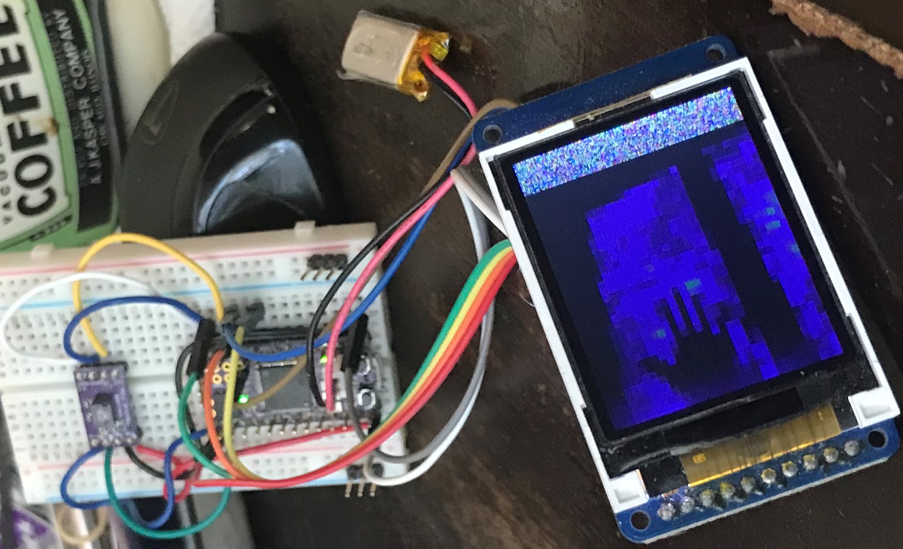
A maker on Elecrow Project Community, Kris Winer has worked on a project using the PAA3905 Breakout Board, in order to create an inexpensive navigation sensor that is suitable for various environments, including low-light conditions. The PAA3905 optical flow sensor, which measures X-Y movement and records low-resolution video at 18 Hz frequency, is linked with the project using a microcontroller such as Arduino. Kris designed a well-documented Arduino sketch that illustrates the use of the sensor for navigation and frame grabbing. For applications where accuracy and energy pricing are vital, the sensor’s low power consumption and flexibility to switch between several light modes make it perfect.
What we achieved
The project was finished successfully, resulting in a functional, low-cost navigation sensor using the PAA3905 Breakout Board. The sensor works well in tracing movement and capturing low-resolution video, making it essential for multiple applications, including those in dim-light surroundings. It is also effective in navigation and frame-capturing systems.
Conclusion
In summary, the PAA3905 Breakout Board project shows how to successfully integrate a low-cost, tiny optical flow sensor that can perform basic imaging and motion tracking in a variety of lighting scenarios. Although it has several benefits for low-power and navigation applications, its dynamic performance and resolution are limited. In general, this study demonstrates how the PAA3905 sensor might improve navigation systems in situations when more conventional systems could falter.
 Case Study 3: Walkie Talkie
Overview
Let's imagine you're on an adventure in the great outdoors and need to stay in contact with your friends or team, but shouting or waving flags aren’t that effective. This is where the modern walkie-talkie comes in. It is designed with cutting-edge technologies to enhance and help communication and safety. In this PCB project, Malik Bruder developed a basic walkie-talkie using NRF24L01 modules, a low-cost module perfect for a hobby PCB project. This PCB project uses the RF24 Audio software specifically designed for audio transmission. While the audio quality may not be the highest, it's ideal for casual communication.
Challenge
Smartphones and other communication devices may not function well in the wilderness with poor network coverage. It's because of modern communication protocols that work the best and fastest within a small area. However, in the case of walkie-talkies, they are made to operate in harsh areas, mainly in forests and basements of the house. Also, mobile phones rely heavily on cellular networks or Wi-Fi connections, which may not always be available or reliable, especially during emergencies or in remote locations. Most communication devices are expensive, which can be an issue if you are planning a small hike or camping trip because almost all of the money can go into them. Meanwhile, walkie-talkie modules can be found pretty cheaply and are easy to set up.
What We Did
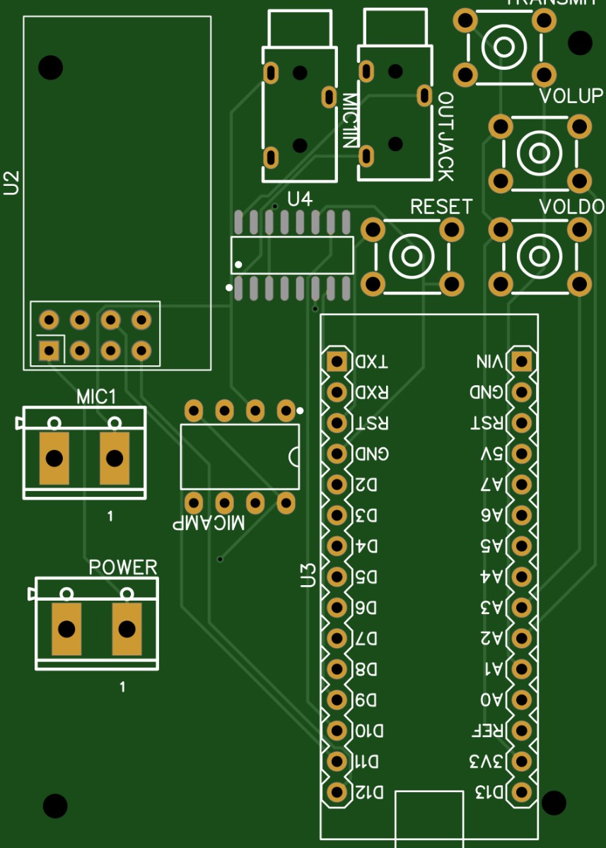
Malik started the PCB project by arranging the materials to use, such as Arduino nano, NRF24L01 module, Audio Amplifier (Line level and output), microphone/audio input, and battery. For the battery, He chose a 9V rechargeable EBL battery from Amazon, along with some battery snaps. The PCB design for the walkie-talkie was also made. After the arrival of the PCB, the components were placed. Some of the components are listed below: SMD Audio amplifier, DIP Audio amplifier, Mic, battery snap, NRF Module, audio jacks, buttons, and finally, an Arduino. After that, the Arduino was flashed with the required program for the PCB project to work.
What we achieved
The PCB project was completed. The walkie-talkie is not that good, as it is a hobby PCB project, but the sound quality is good enough to play around with. Some troubleshooting, such as placing some decoupling capacitors, had to be done in order for it to work seamlessly.
Conclusion
This PCB project was to demonstrate how a walkie-talkie module works. It is made from low-cost materials, so almost everyone can learn from it. This also presents a practical and affordable communication solution suited for hobbyists and casual users. While it may not be able to offer the highest quality, its simple, reliable, and independent nature from network infrastructure makes it an excellent choice for a variety of applications such as outdoor adventures and emergency situations. Finally, this PCB project demonstrates how modern technology can provide effective solutions for everyday use by addressing the challenges related to other devices, such as limited range, network dependence, and battery life issues.

