Currency
Toggle Nav

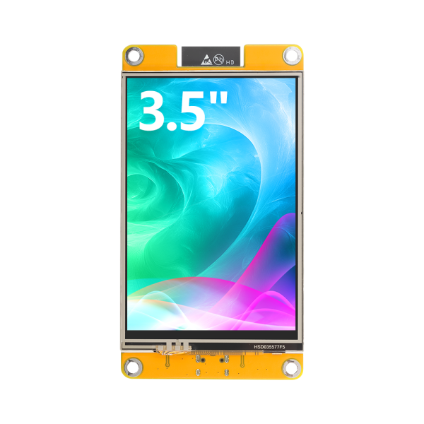


3.5” 320x480 ESP32 LCD Touch Display | With WiFi and BT/BLE
$14.90
Availability:
In stock
SKU
DHO28035B
Weight
120g
Related Products:


×
 Add to cart successfully!


Customers Who View This Item Also Bought
[High-performance Chip] Equipped with ESP32--WROOM-32E dual-core processor, the main frequency can reach 240MHz;
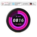
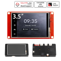
[3.5” Touch Screen] With 320x480 resolution and resistive touch;
[Rich Interfaces] Comes with rich interfaces for connecting like SPI, UART and other peripherals;
[Audio Support] Supports external speakers and can play audio to meet multimedia development needs;
[Lightweight and portable, safe charging] Comes with battery charging management circuit, supports external lithium battery, lightweight and portable
Description
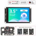
This 3.5“ display is a high-performance development module integrates the ESP32--WROOM-32E module. It has powerful development capabilities and rich resources, providing great convenience for developers. It is equipped with a 3.5-inch screen with a resolution of 320x480 and supports rich color display of up to 262K colors (RGB666), ensuring clear images and bright colors. The module provides a variety of interfaces, including SPI, UART, etc., which are convenient for connecting various peripherals to meet diverse development needs.
In addition, it supports external speakers to play audio, has its own RGB three-color indicator for rich status indication, and is also equipped with a resistive touch screen for convenient human-computer interaction. It uses a standard TYPE-C interface to facilitate program downloads and power supply, and comes with a micro TF card slot for easy expansion of storage space. It supports external lithium batteries, is lightweight and portable, and has a built-in battery charging management circuit to ensure safe battery charging and discharging. We also provide a wealth of sample programs and technical support to help developers get started quickly. It is suitable for smart home, industrial control and maker projects.
Customized requests can be discussed(based on MOQ), you can contact us at service@elecrow.com
Feature
- Built-in ESP32--WROOM-32E module, main frequency up to 240MHz, excellent performance
- 3.5-inch color screen, 320x480 resolution, support 262K colors (RGB666), rich display colors
- Rich interfaces for connecting various peripherals (SPI, UART and other peripherals)
- Support external speakers, play audio
- Built-in RGB three-color indicator lights, rich indication status
- Resistive touch screen comes with a pen
- TYPE-C interface, convenient for program download and power supply
- On board micro TF card slot, convenient for expanding storage
- Support external lithium battery, lightweight and portable
- Built-in battery charging management circuit to ensure safe charging and discharging of batteries
Application Scenario
Interface Definition

Interface Function Description
|
Interface Name |
Description |
Connect Type |
|
Serial port |
It can be used for serial debugging, downloading,and communication. An external USB to serial port module is required. |
1.25mm 4P |
|
Battery Interface |
Used to connect 3.7V polymer lithium battery, charge the battery through the battery charge management circuit,can also be used for battery power supply. |
1.25mm 2P |
|
BOOT Key |
Used to enter download mode or key test. |
|
|
Type-C Interface |
Used for module power supply and download programs. |
|
|
RESET Key |
Used for ESP32 master control and LCD reset, level reset after pressing. |
|
|
Expand the input pin |
IO35 and IO39 are two input-only IOs that are used to access input signals. |
1.25mm 2P |
|
Speaker Interface |
Used to access the speaker to play audio. |
1.25mm 2P |
|
SPI peripheral interface |
For external connection to devices that use IIC communication. |
1.25mm 4P |
|
I2C peripheral interface |
For external connection to devices that use IIC communication. |
1.25mm 4P |
Specification
|
ESP32 Module |
|
|
Chip |
ESP32--WROOM-32E |
|
CPU |
ESP32-D0WD-V3,Xtensa dual-core 32-bit LX6 microprocessor |
|
Frequency |
240MHz(Max) |
|
Memory |
48KB ROM+520KB SRAM+16KB RTC SRAM+4MB external QSPI Flash |
|
WIFI |
2.4GHz and 802.11b/g/n modes |
|
Bluetooth |
Bluetooth V4.2BR /EDR and Bluetooth LE standards |
|
Screen |
|
|
Panel Size |
3.5 inch |
|
Panel Type |
TN TFT |
|
Touch Screen Type |
Resistive touch screen |
|
Resolution |
320xRGBx480(pixels) |
|
Active Area |
48.96(W)x73.44(H) |
|
Number of Colors |
Max: 262K(RGB666); Common: 65K(RGB565) |
|
Display Driver IC |
ST7796U |
|
Touch Driver IC |
XPT2046 |
|
Communication Interface |
SPI |
|
Pixel Size |
0.153(H)x0.153(mm) |
|
Brightness(TYP) |
300 cd/m2 |
|
Backlight Type |
White LED*6 |
|
Other |
|
|
Charging Voltage |
Range: 4.2 to 6.5V; Typical value: 5V |
|
Working Voltage |
5.0V |
|
Charging Current |
Max: 500mA; Module Actual value: 290mA |
|
Backlight Current |
104mA |
|
Charging Saturation Voltage |
4.24V |
|
Rechargeable Battery Spec |
3.7V polymer lithium battery(It doesn’t include the battery) |
|
Power |
0.89W(Display only works) |
|
Module Size |
55.50(W)x101.50(H)x5.80(D)(mm) |
|
Operating Temperature |
-10~60℃ |
|
Storage Temperature |
-20~70℃ |
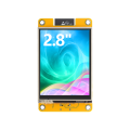
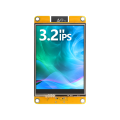
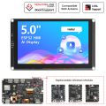
Different Size Comparison
|
Spec |
|||
|
Chip |
ESP32-WROOM-32E |
||
|
CPU |
ESP32-D0WD-V3,Xtensa dual-core 32-bit LX6 microprocessor |
||
|
Frequency |
240MHz(Max) |
||
|
Memory |
48KB ROM+520KB SRAM+16KB RTC SRAM+4MB external QSPI Flash |
||
|
WIFI |
2.4GHz and 802.11b/g/n modes |
||
|
Bluetooth |
Bluetooth V4.2BR /EDR and Bluetooth LE standards |
||
|
Panel Type |
TN TFT |
IPS TFT |
TN TFT |
|
Touch Screen Type |
Resistive touch screen |
||
|
Resolution |
240xRGBx320(pixels) |
320xRGBx480(pixels) |
|
|
Active Area |
43.20(W)x57.60(H) |
48.60(W)x64.80(H) |
48.96(W)x73.44(H) |
|
Number of Colors |
Max: 262K(RGB666); Common: 65K(RGB565) |
||
|
Display Driver IC |
ILI9341V |
ST7789P3 |
ST7796U |
|
Touch Driver IC |
XPT2046 |
||
|
Communication Interface |
SPI |
||
|
Pixel Size |
0.153(H)x0.153(mm) |
0.153(H)x0.153(mm) |
0.153(H)x0.153(mm) |
|
Brightness(TYP) |
260 cd/m2 |
300 cd/m2 |
|
|
Backlight Type |
White LED*4 |
White LED*6 |
|
|
Charging Voltage |
Range: 4.2 to 6.5V; Typical value: 5V |
||
|
Working Voltage |
5.0V |
||
|
Charging Current |
Max: 500mA; Module Actual value: 290mA |
||
|
Backlight Current |
75mA |
104mA |
104mA |
|
Charging Saturation Voltage |
4.24V |
||
|
Rechargeable Battery Spec |
3.7V polymer lithium battery(It doesn’t include the battery) |
||
|
Power |
0.65W(Display only works) |
0.8W(Display only works) |
0.89W(Display only works) |
|
Module Size |
50.00(W)x86.00(H)x5.60(D)(mm) |
55.00(W)x93.00(H)x5.70(D)(mm) |
55.50(W)x101.50(H)x5.80(D)(mm) |
|
Operating Temperature |
-10~60℃ |
||
|
Storage Temperature |
-20~70℃ |
||
ESP32 Pin Assignment
|
Onboard Equipment |
ESP32 Connect Pins |
Pin Description of Onboard Equipment |
|
LCD |
IO15 |
LCD screen selection control signal, low level effective |
|
IO2 |
LCD command/data selection control signal High Level: data, low Level:command |
|
|
IO14 |
SPI bus clock signal(shared by LCD and touch screen) |
|
|
IO13 |
SPI bus write data signal(shared by LCD and touch screen) |
|
|
IO12 |
SPI bus read data signal(shared by LCD and touch screen) |
|
|
EN |
LCD reset control signal, low level reset(share reset pin with ESP32-32E master) |
|
|
IO27 |
LCD backlight control signal(high level backlight on, low level backlight off) |
|
|
Resistive Touch Screen |
IO14 |
SPI bus clock signal(shared by touch screen and LCD) |
|
IO13 |
SPI bus write data signal(touch screen and LCD screen shared) |
|
|
IO12 |
SPI bus read data signal(shared by touch screen and LCD screen) |
|
|
IO33 |
Resistive touch screen chip selection control signal,low level effective |
|
|
IO36 |
Resistive touch screen touch interrupt signal, generates touch when input low level to master |
|
|
RGB Three-color Light |
IO22 |
Red LED light(common anode, low level on, high level off) |
|
IO16 |
Green LED light(common anode, low level on, high level off) |
|
|
IO17 |
Blue LED light(common anode, low level on, high level off) |
|
|
MicroSD Card |
IO5 |
SD card select signal, low level effective |
|
IO23 |
SD card SPI bus write data signal(shared by MicroSD card and SPI peripheral) |
|
|
IO18 |
SD card SPI bus clock signal(shared by MicroSD card and SPI peripheral) |
|
|
IO19 |
SD card SPI bus read data signal(shared by MicroSD card and SPI peripheral) |
|
|
Audio |
IO4 |
Audio enable signal,low level enable,high level disable |
|
IO26 |
Audio signal DAC output signal |
|
|
KEY |
IO0 |
Download mode Select button(Press and hold the button to power on, then release to enter download mode) |
|
EN |
ESP32-23E reset button, low level reset(shared with LCD reset) |
|
|
Serial Port |
RXD0(IO3) |
ESP32-32E serial port receiving signal(if the serial port is not used, it can be used as ordinary IO) |
|
TXD0(IO1) |
ESP32-32E serial port sends signals(if the serial port is not used, it can be used as ordinary IO) |
|
|
Battery |
IO34 |
Battery voltage ADC value Get Signal (input) |
|
SPI Peripheral |
IO21 |
SPI peripheral chip selection signal, low level effective(if the SPI device is not used, it can be used for ordinary IO) |
|
IO18 |
SPI bus clock pin for SPI peripherals (SPI peripherals are shared with MicroSD cards, if SPI devices or SD cards are not used, ordinary IO can be used) |
|
|
IO19 |
The SPI bus read data pin of the SPI peripheral (SPI peripherals are shared with MicroSD cards, if SPI devices or SD cards are not used, ordinary IO can be used) |
|
|
IO23 |
The SPI bus of the SPI peripheral writes data pins (SPI peripherals are shared with MicroSD cards, if SPI devices or SD cards are not used, ordinary IO can be used) |
|
|
I2C Peripheral |
IO25 |
I2C bus clock pin for I2C peripherals (can be used as normal IO if I2C device is not used) |
|
IO32 |
I2C bus data pins for I2C peripherals (can be used for ordinary IO if I2C devices are not used) |
|
|
NC |
IO35 |
It can only be used as input IO |
|
IO39 |

Package List
- 1x 3.5 inch ESP32 LCD Module
- 1x Type-C Cable
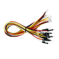
- 1x 4Pin Cable
Wiki & External Links
Write Your Own Review